Teledyne 306WA - Analog trace oxygen analyzer User Manual
Page 14
3-2
3.0 Installation
3.0 Installation
3.0 Installation
3.0 Installation
3.0 Installation
Model 306W
Model 306W
Model 306W
Model 306W
Model 306WA
A
A
A
A
TELEDYNE ELECTRONIC TECHNOLOGIES
Analytical Instruments
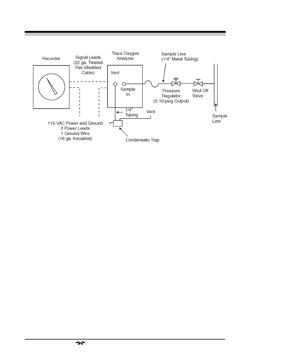
Figure 3: Typical System Layout
3.3 Sample Connections
3.3 Sample Connections
3.3 Sample Connections
3.3 Sample Connections
3.3 Sample Connections
The sample line is connected at the back of the analyzer case as de-
picted in Figure 5. Use care in assembling any part of the sampling system
to avoid leaks. Oxygen can diffuse into the system through small leaks even
when sample pressure is much greater than atmospheric pressure.
1. Connectors
Connectors
Connectors
Connectors
Connectors. Use straight tube connectors where possible.
This facilitates removal of the analyzer section from the case
during maintenance or service.
2. Lines
Lines
Lines
Lines
Lines. Lines should consist of metallic tubing, since oxygen can
diffuse through plastic. Use continuous tubing where possible.
3. Vent
Vent
Vent
Vent
Vent. The analyzed sample is vented through the back of the
unit as shown in Figure 5.
The analyzer should have a vent line of ¼" diameter tubing at least two
feet long, running downward
downward
downward
downward
downward from the vent connection. This is to prevent
air from diffusing into the reservoir and dissolving into the humidifier make-
up water.
If it is not desirable to vent the sample into the atmosphere, a vent line
to carry the sample to a suitable venting area will be required. The sample
leaves the vent connection of the analyzer saturated with water vapor at a
temperature somewhat above ambient, so a suitable trap to remove conden-
sate without plugging the vent line will be required. The vent line should
also be arranged so that it cannot become plugged by dirt or dust.