Installation, Stack and flue, Pressure gauges – Fulton Classic ICX or FB-F Vertical Tubeless Boilers (Hot Water), Gas_Oil Fired User Manual
Page 19
Questions? Call (315) 298-5121, or visit us online at www.fulton.com
SECTION 2
ICW-IOM-2014-0410
INSTALLATION
2-13
!
WARNING
All information in this manual is for
reference and guidance purposes,
and does not substitute for required
professional training, conduct,
and strict adherence to applicable
jurisdictional/professional codes and
regulations.
Assure all electrical connections are
powered down prior to attempting
replacement or service of electrical
components or connections of the
equipment.
Cements for plastic pipe should
be kept away from all sources of
ignition. Proper ventilation should
be maintained to reduce the hazard
and to minimize breathing of cement
vapors.
No shutoff of any kind may be
placed between the safety relief
valve and the equipment, or in the
discharge pipe between such valve
and the atmosphere. Doing so may
cause accidental explosion from
overpressure.
Discharge from safety relief valve
must be confi gured so that there
is no danger of scalding personnel
or causing equipment damage.
Provisions must be made to properly
drain safety relief valve discharge
piping.
For reasons of safety, the hot exhaust
gas duct and chimney must be
insulated or shielded within the
locality of the heater in compliance
with local codes and regulations.
4
CAUTION
The stack arrangement and draft
conditions should be in accordance
with the information in this manual for
proper performance of the equipment.
Pressure Gauges
The range in which readings are expected to fall should comprise mid-scale
on the pressure gauge chosen. Pressure gauges must be able to withstand
overpressure equal to the rating of the safety relief valves, normally 100 psig.
NOTE:
The Water temperature pressure gauge should not be altered in any way.
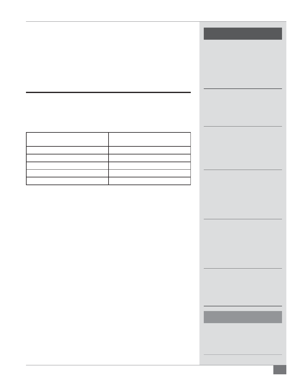
Stack and Flue
An appropriately sized stack should be connected to the fl ue gas outlet at the
boiler. The proper fl ue size and draft control is most important for proper burner
operation. See Table 4.
TABLE 4 - MINIMUM FLUE SIZES
Model
Minimum Flue Size
inches (mm)
6
6 (152)
10
6 (152)
15
8 (203)
20
10 (254)
30
12 (305)
The fl ue must be as large or larger than the outlet on the vessel. Avoid fl ue
piping and elbows by placing the equipment as close as possible to the chimney.
Adhere to the following for stack and fl ue installation (see Figure 3):
1. Ensure the stack rises continuously to the connection at the chimney and
contains no more than two bends at 45 degree angles or less. If required,
as a result of space limitations, one 90 degree elbow (or tee) can be fi tted
at the back of the vessel.
2. Ensure 2 feet (0.6 m) of straight, horizontal fl ue before any change in
direction, fi tting or draft regulator. This is to prevent potential pilot or
main fl ame failures due to back pressure build up during ignition. Any
alternative stack arrangement must supply negative 0.02 to 0.04”wc.
3. Ensure the run in the total distance of stack ducting, as measured in a
straight line from the outlet of the boiler to the outlet of the stack, does
not exceed 25% of the rise. With the exception of the duct run previously
described, horizontal sections of ducting must be avoided and should not
exceed 4 feet (1.2 m) total. See Figure 3.
4. Ensure the stack, chimney, and any components associated with the stack,
such as heat reclaimers or assist fans, are constructed from material that is
rated for a 1000 F (538 C) operating temperature.
5. Ensure the stack and chimney material complies with all applicable codes.
6. Make adequate provisions for the support of the weight of the chimney
and stack to avoid having a load imparted to the outlet connection of the