Alliance Laundry Systems PHM1401C User Manual
Page 55
© Copyright, Alliance Laundry Systems LLC – DO NOT COPY or TRANSMIT
Diagnostic
53
F8138801
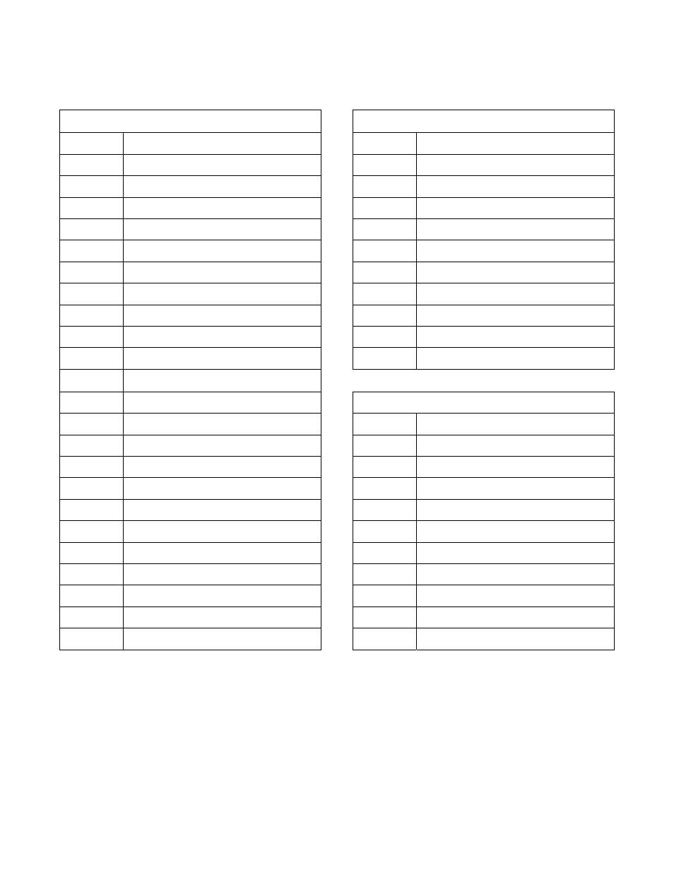
Abbreviations for the Inputs and Outputs are defined
in the following table:
Outputs
Outputs
AX1
Auxiliary Fill or Internal Supply 5
RFB
Reuse Fill B
AX2
Unused
RUN
VF Motor Drive Forward
AX3
Recirculation or Reuse Drain A
RV
Reverse Motor Contactor
AX4
External Signal (Optional Audio)
S1
Internal Supply 1
AX5
Reuse Wash Drain
S2
Internal Supply 2
CF
Cold Fill
S3
Internal Supply 3
CS
Cold Spray
S4
Internal Supply 4
DN
Drain
SP1
Extract Motor Contactor
DR
Door Unlock
SPD1
VF Motor Drive Speed Select #1
ES1
External Supply 1
SPD2
VF Motor Drive Speed Select #2
ES2
External Supply 2
SPD3
VF Motor Drive Speed Select #3
ES3
External Supply 3
ES4
External Supply 4
Inputs
ES5
External Supply 5
BAL
VF Drive Balance
ES6
External Supply 6
DFLT
Drive Fault
ES7
External Supply 7
DL
Door Lock
ES8
External Supply 8
DR
Door
FW
Forward Motor Contactor
FSW
Frame Balance Switch
HF
Hot Fill
OSW
Optional Switch (UW150 Joggle)
HS
Hot Spray
PAUS
External Dispenser Pause A and/or B
HT
Heater
PSW
Low Level Pressure Switch
RDB
Reuse Drain B
RS
Rotation Sensor (Non-Zero RPM)
REV
VF Motor Drive Reverse
TS
Thermostat (Temp Satisfied)
RFA
Reuse Fill A
WL
Water Level (Level Satisfied)
Table 5