Fig. 0712 series flush la tch set, Exploded view – PERKO 0712 User Manual
Page 2
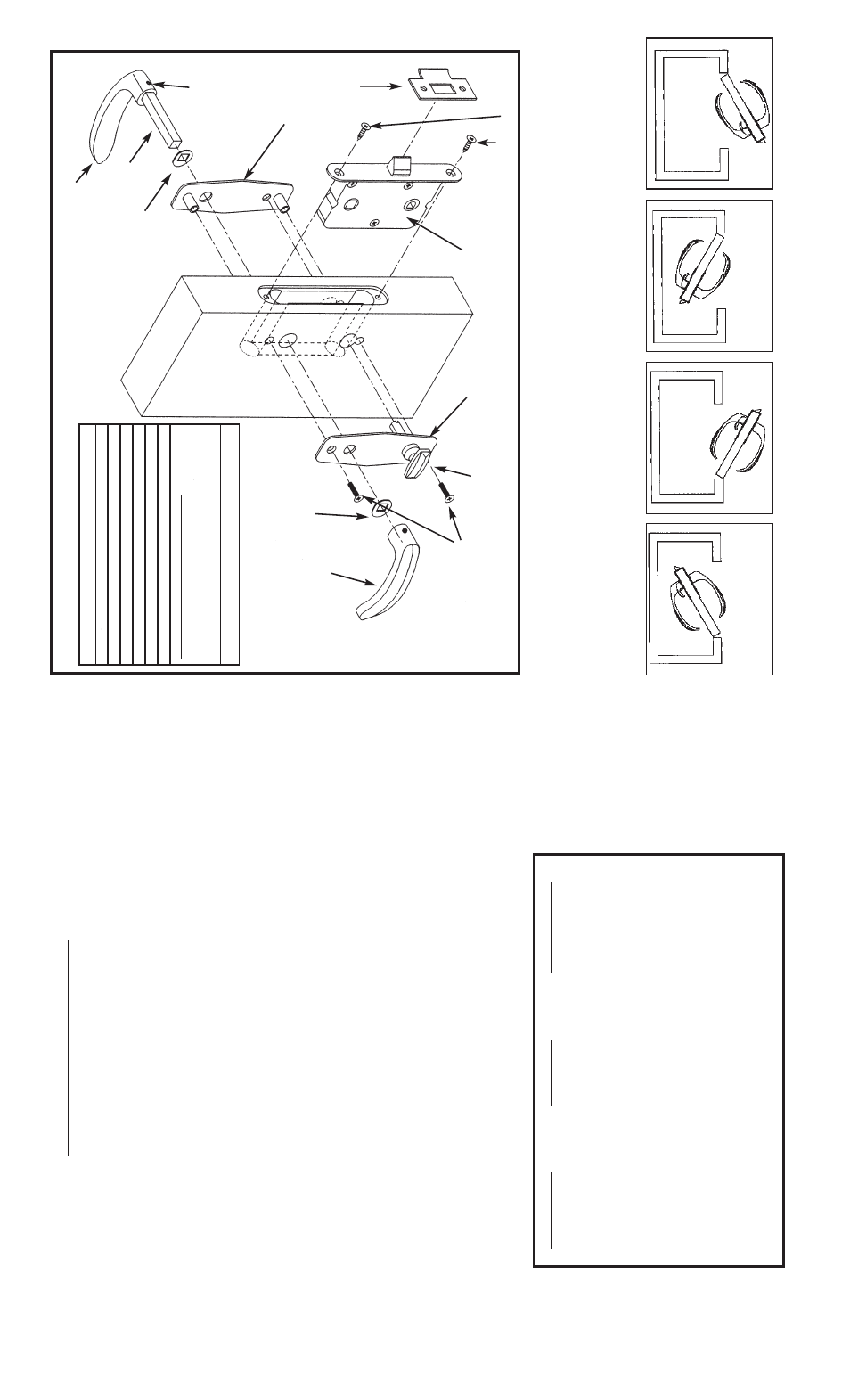
FIG. 0712 SERIES FLUSH LA
TCH SET
MOUNTING INSTRUCTIONS
Read all instr
uctions bef
or
e pr
oceeding.
This ser
ies of f
lush latc
h sets is designed to be mounted on
door
s 3/4 inc
h
to 1-1/2 inc
hes thic
k.
1).
T
ape
T
emplate 1 on door at the desir
ed location.
2).
Mar
k thr
ough template f
or tw
o 9/16”
diameter holes (“
A
”) and tw
o 9/32”
diameter holes (“B”)
3).
Dr
ill all 4 holes.
4).
T
ape
T
emplate 2 on door at the desir
ed location Lining up Holes
“C”
and the
centerline r
e
fe
rence (C/L) with
T
emplate 1.
Note:
The bev
el is not in the center of the
Case Assemb
ly
.
5).
Mar
k thr
ough
T
emplate 2 f
or tw
o 3/32”
diameter holes (“C”) and tw
o 5/8”
diameter
holes (“D”).
6).
Dr
ill (“C”) holes 1 inc
h deep and (“D”) holes 2-3/16”
deep.
7).
Route door out to depth (“E”) sho
wn on template betw
een the tw
o 5/8”
diameter holes using a 1/2 inc
h diameter r
outing bit.
8).
Route door out to depth (“F”) sho
wn on template using a 3/4 inc
h diameter
routing bit.
9).
Remo
v
e handles and separ
ate the escutc
heons.
Slide case assemb
ly
into door
.
10).
F
asten case assemb
ly
to door with (2) #6 f
lat head scr
e
w
s.
(Supplied).
11).
Ref
asten escutc
heons.
Attac
h
'L' handles to the shaft and install in latc
h set with
squar
e w
asher
s.
T
ighten set scr
e
ws on lev
er handles.
12).
Mount str
ike plate to door fr
ame with (2) #6 f
lat head scr
e
ws (Supplied).
Reliev
e
under the str
ike plate in or
der to allo
w the bev
el to full
y e
xtend with 1/8”
minimum
c
lear
ance when the latc
h is c
losed.
13).
NO
TE:
The latc
h set has a saf
ety unlatc
h f
eatur
e on the outside that can be
activ
ated b
y
inser
ting a small b
lade scr
e
wdr
iv
er and tur
ning.
Exploded View
Handle
Handle
Set Scr
e
w
Shaft
#6 Scr
e
w (Supplied)
W
asher
W
asher
Case Assemb
ly
LEFT INW
ARD
LEFT OUTW
ARD
RIGHT OUTW
ARD
RIGHT INW
ARD
DETERMINING
THE HAND OF
THE LA
TCH SET
.
NOTE:
The pr
iv
acy latc
h handle should alw
ays be mounted on the door’
s inter
ior side
Inside Chr
ome
Escutc
heon
Pr
iv
acy
Handle
Outside Chr
ome
Escutc
heon
#6 Scr
e
w
(Supplied)
Catalog No.
Door Size
T
ype of Latch
0712001LIC
3/4 to 1
Left Inw
ar
d or
Right Outw
a
rd
0712001RIC
3/4 to 1
R
ight Inw
a
rd
or
Left Outw
ar
d
0712002LIC
1 to 1-1/4
Left Inw
ar
d or
Right Outw
a
rd
0712002RIC
1
to 1-1/4
Right Inw
a
rd
or
Left Outw
ar
d
0712003LIC
1-1/4 to 1-1/2
Left Inw
ar
d or
Right Outw
a
rd
0712003RIC
1-1/4 to 1-1/2
Right Inw
a
rd
or
Left Outw
ar
d
Item
Cat. Nos
Handle Assy for 3/4 to 1 Door*
071200198A
Handle Assy for 1 to 1-1/4 Door*
071200298A
Handle Assy for 1-1/4 to 1-1/2 Door*
071200398A
Case Assembly
071200088B
Inside Chrome Escutcheon
071200099C
Outside Chrome Escutcheon
071200099D
Privacy Latch Handle Assy (Includes Shaft)
Privacy Handle Assy for 3/4-1 Door
071200188A
Privacy Handle Assy for 1 to 1-1/4 Door
071200288A
Privacy Handle Assy for 1-1/4 to 1-1/2 Door
071200388A
Strike Plate
0912000CHR
SP
ARE P
ARTS
*Note:
Handle
Assemb
ly
inc
ludes 2 lev
er handles,
set scr
e
ws,
w
asher
s and shaft.
Note:
Left Inw
ar
d/Right Outw
ar
d ar
e Inter
c
hang
ea
b
le.
Right Inw
a
rd/Left Outw
ar
d ar
e Inter
c
hang
ea
b
le.
Str
ike
Plate