PERKO 0591 User Manual
Mounting template
Cat. Nos. 0540, 0541, 0542, 0543, 0580, 0581,
0582, 0583, 0590 & 0591 Series Combination Gas/Vent Fills
Installation and Operation Instructions
PLEASE READ ALL INSTRUCTIONS BEFORE PROCEEDING
1. Select mounting location:
- In accordance with A.B.Y.C., U.S. Coast Guard and E.P.A. requirements and regulations.
- Surface must be flat and provide adequate clearance to remove the cap.
- Allow for adequate clearance under fill for routing fill and vent hose, which must be selected and
installed in accordance with A.B.Y.C. requirements and U.S. Coast Guard Safety Standards for
Small Boat Fuel Systems (33 CFR 183).
-- C
CO
ON
NS
SIID
DE
ER
R T
TH
HE
E L
LIIM
MIIT
TA
AT
TIIO
ON
NS
S O
OF
F A
A M
MA
AR
RIIN
NE
E F
FU
UE
EL
L V
VE
EN
NT
T::
A)
DO NOT LOCATE ON A SURFACE THAT CAN BECOME SUBSTANTIALLY SUBMERGED
OR FLOODED, OTHERWISE WATER CAN BE DRAWN INTO THE SYSTEM DURING VENT
OPERATION. AN ACCESSORY MOUNTING RING (PERKO CAT. NO. 0540RNGBLK) IS
AVAILABLE TO RAISE THE FILL/VENT ABOVE THE MOUNTING SURFACE.
B)
ACCOMODATE FUGITIVE LIQUID FUEL EMISSIONS THAT RESULT FROM IN-TANK FUEL
SURGES.
2.
Attach mounting template to selected mounting surface and orient for desired position of fill/vent con-
nections and for ease of insertion of the fuel nozzle into the fill neck. Drill where indicated. Be sure to
drill the 3/4 inch hole before drilling the 2-1/16 inch hole.
NOTE: The 2-1/16” dimension of the larger hole is sized to provide mounting surface support
to the fill body. DO NOT use larger size cutter or drill.
3.
Mount fill using #8 pan head screws. Caulk if necessary.
4.
Attach and clamp 1-1/2 inch fill hose and 5/8 inch vent hose in accordance with the above referenced
standards.
5.
The vent system requires that the surge valve feels loose in order to operate properly. Remove two
screws under cap to access flame arrestor screen for cleaning.
NOTE: Plastic fuel fills should NOT be grounded.
(1). American Boat & Yacht Council, Inc.
(2). U.S. Coast Guard
(3). E.P.A.
3069 Soloman’s Island Rd.
Washington, D.C. 20593
401 “M” Street S.W.
Edgewater, Maryland 21307
(or your local C.G. office)
Washington, D.C. 20460
08/05
0540INS1
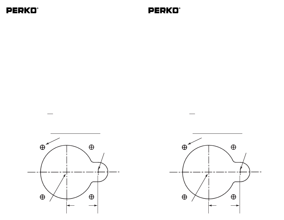
Drill 3/4” Dia. Hole
(Drill First)
1-7/32”
Drill for #8 Size Mounting Screws
4 Places (Drill Last)
Drill 2-1/16” Dia. Hole
(Drill Second)
See Note after instruction #2
MOUNTING TEMPLATE
Cat. Nos. 0540, 0541, 0542, 0543, 0580, 0581,
0582, 0583, 0590 & 0591 Series Combination Gas/Vent Fills
Installation and Operation Instructions
PLEASE READ ALL INSTRUCTIONS BEFORE PROCEEDING
1. Select mounting location:
- In accordance with A.B.Y.C., U.S. Coast Guard and E.P.A. requirements and regulations.
- Surface must be flat and provide adequate clearance to remove the cap.
- Allow for adequate clearance under fill for routing fill and vent hose, which must be selected and
installed in accordance with A.B.Y.C. requirements and U.S. Coast Guard Safety Standards for
Small Boat Fuel Systems (33 CFR 183).
-- C
CO
ON
NS
SIID
DE
ER
R T
TH
HE
E L
LIIM
MIIT
TA
AT
TIIO
ON
NS
S O
OF
F A
A M
MA
AR
RIIN
NE
E F
FU
UE
EL
L V
VE
EN
NT
T::
A)
DO NOT LOCATE ON A SURFACE THAT CAN BECOME SUBSTANTIALLY SUBMERGED
OR FLOODED, OTHERWISE WATER CAN BE DRAWN INTO THE SYSTEM DURING VENT
OPERATION. AN ACCESSORY MOUNTING RING (PERKO CAT. NO. 0540RNGBLK) IS
AVAILABLE TO RAISE THE FILL/VENT ABOVE THE MOUNTING SURFACE.
B)
ACCOMODATE FUGITIVE LIQUID FUEL EMISSIONS THAT RESULT FROM IN-TANK FUEL
SURGES.
2.
Attach mounting template to selected mounting surface and orient for desired position of fill/vent con-
nections and for ease of insertion of the fuel nozzle into the fill neck. Drill where indicated. Be sure to
drill the 3/4 inch hole before drilling the 2-1/16 inch hole.
NOTE: The 2-1/16” dimension of the larger hole is sized to provide mounting surface support
to the fill body. DO NOT use larger size cutter or drill.
3.
Mount fill using #8 pan head screws. Caulk if necessary.
4.
Attach and clamp 1-1/2 inch fill hose and 5/8 inch vent hose in accordance with the above referenced
standards.
5.
The vent system requires that the surge valve feels loose in order to operate properly. Remove two
screws under cap to access flame arrestor screen for cleaning.
NOTE: Plastic fuel fills should NOT be grounded.
(1). American Boat & Yacht Council, Inc.
(2). U.S. Coast Guard
(3). E.P.A.
3069 Soloman’s Island Rd.
Washington, D.C. 20593
401 “M” Street S.W.
Edgewater, Maryland 21307
(or your local C.G. office)
Washington, D.C. 20460
08/05
0540INS1
Drill 3/4” Dia. Hole
(Drill First)
1-7/32”
Drill for #8 Size Mounting Screws
4 Places (Drill Last)
Drill 2-1/16” Dia. Hole
(Drill Second)
See Note after instruction #2
MOUNTING TEMPLATE
PERKO, INC.
16490 N.W. 13th Avenue
Miami, Fl. 33169-5707
www.perko.com
PERKO, INC.
16490 N.W. 13th Avenue
Miami, Fl. 33169-5707
www.perko.com