PERKO 1318 User Manual
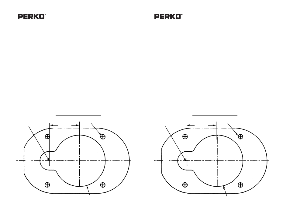
Drill for #10 screws (4), 1/16” dia, Mounting template
Cat. Nos. 1318 Series Combination Fill/Vents
Installation and Operation Instructions
1. Select mounting location:
- In accordance with A.B.Y.C., U.S. Coast Guard and E.P.A. requirements and regulations.
- Surface must be flat and provide adequate clearance to remove the cap.
- Allow for adequate clearance under fill for routing fill and vent hose, which must be selected and installed in
accordance with A.B.Y.C. requirements and U.S. Coast Guard Safety Standards for Small Boat Fuel Systems
(33 CFR 183).
-- C
CO
ON
NS
SIID
DE
ER
R T
TH
HE
E L
LIIM
MIIT
TA
AT
TIIO
ON
NS
S O
OF
F A
A M
MA
AR
RIIN
NE
E F
FU
UE
EL
L V
VE
EN
NT
T::
A
A))
D
DO
O N
NO
OT
T L
LO
OC
CA
AT
TE
E O
ON
N A
A S
SU
UR
RF
FA
AC
CE
E T
TH
HA
AT
T C
CA
AN
N B
BE
EC
CO
OM
ME
E S
SU
UB
BS
ST
TA
AN
NT
TIIA
AL
LL
LY
Y S
SU
UB
BM
ME
ER
RG
GE
ED
D O
OR
R
F
FL
LO
OO
OD
DE
ED
D,, O
OT
TH
HE
ER
RW
WIIS
SE
E W
WA
AT
TE
ER
R C
CA
AN
N B
BE
E D
DR
RA
AW
WN
N IIN
NT
TO
O T
TH
HE
E S
SY
YS
ST
TE
EM
M D
DU
UR
RIIN
NG
G V
VE
EN
NT
T
O
OP
PE
ER
RA
AT
TIIO
ON
N..
B
B))
A
AC
CC
CO
OM
MO
OD
DA
AT
TE
E F
FU
UG
GIIT
TIIV
VE
E L
LIIQ
QU
UIID
D F
FU
UE
EL
L E
EM
MIIS
SS
SIIO
ON
NS
S T
TH
HA
AT
T R
RE
ES
SU
UL
LT
T F
FR
RO
OM
M
IIN
N--T
TA
AN
NK
K F
FU
UE
EL
L S
SU
UR
RG
GE
ES
S..
2. Non-metallic fills do not need to be grounded or bonded.
3. Attach mounting template to selected mounting surface and orient for desired position of fill/vent connections and
for ease of insertion of the fuel nozzle into the neck. Drill where indicated, drilling the 3/4 inch hole first.
NOTE: The 2-1/16” dimension of the larger hole is sized to provide mounting surface support to fill the
body. DO NOT use larger size cutter or drill.
4. Mount fill using #10 Round head or Pan head screws. Caulk if necessary.
5. Attach and clamp fill and vent hoses, also in accordance with the above referenced
requirements.
6. The vent system requires that the surge valve feels loose in order to operate properly. Unscrew
collar to remove surge valve and access flame arrestor screen for cleaning.
(1). American Boat & Yacht Council, Inc. (2). U.S. Coast Guard (3). E.P.A.
3069 Solomon’s Island Road
Washington,D.C.20593 401”M” Street S.W.
Edgewater, Maryland 21037
(or you local C.G. office) Washington, D.C. 20460
3/02
1318INS1
Drill for #10 Screws (4)
Drill 3/4” Dia. Hole
(Drill First)
2-1/16” Dia.
Hing
e Side
PERKO, INC.
16490 N.W. 13th Avenue
Miami, FL 33169-5707
www.perko.com
PERKO, INC.
16490 N.W. 13th Avenue
Miami, FL 33169-5707
www.perko.com
1-7/32”
MOUNTING TEMPLATE
Cat. Nos. 1318 Series Combination Fill/Vents
Installation and Operation Instructions
1. Select mounting location:
- In accordance with A.B.Y.C., U.S. Coast Guard and E.P.A. requirements and regulations.
- Surface must be flat and provide adequate clearance to remove the cap.
- Allow for adequate clearance under fill for routing fill and vent hose, which must be selected and installed in
accordance with A.B.Y.C. requirements and U.S. Coast Guard Safety Standards for Small Boat Fuel Systems
(33 CFR 183).
-- C
CO
ON
NS
SIID
DE
ER
R T
TH
HE
E L
LIIM
MIIT
TA
AT
TIIO
ON
NS
S O
OF
F A
A M
MA
AR
RIIN
NE
E F
FU
UE
EL
L V
VE
EN
NT
T::
A
A))
D
DO
O N
NO
OT
T L
LO
OC
CA
AT
TE
E O
ON
N A
A S
SU
UR
RF
FA
AC
CE
E T
TH
HA
AT
T C
CA
AN
N B
BE
EC
CO
OM
ME
E S
SU
UB
BS
ST
TA
AN
NT
TIIA
AL
LL
LY
Y S
SU
UB
BM
ME
ER
RG
GE
ED
D O
OR
R
F
FL
LO
OO
OD
DE
ED
D,, O
OT
TH
HE
ER
RW
WIIS
SE
E W
WA
AT
TE
ER
R C
CA
AN
N B
BE
E D
DR
RA
AW
WN
N IIN
NT
TO
O T
TH
HE
E S
SY
YS
ST
TE
EM
M D
DU
UR
RIIN
NG
G V
VE
EN
NT
T
O
OP
PE
ER
RA
AT
TIIO
ON
N..
B
B))
A
AC
CC
CO
OM
MO
OD
DA
AT
TE
E F
FU
UG
GIIT
TIIV
VE
E L
LIIQ
QU
UIID
D F
FU
UE
EL
L E
EM
MIIS
SS
SIIO
ON
NS
S T
TH
HA
AT
T R
RE
ES
SU
UL
LT
T F
FR
RO
OM
M
IIN
N--T
TA
AN
NK
K F
FU
UE
EL
L S
SU
UR
RG
GE
ES
S..
2. Non-metallic fills do not need to be grounded or bonded.
3. Attach mounting template to selected mounting surface and orient for desired position of fill/vent connections and
for ease of insertion of the fuel nozzle into the neck. Drill where indicated, drilling the 3/4 inch hole first.
NOTE: The 2-1/16” dimension of the larger hole is sized to provide mounting surface support to fill the
body. DO NOT use larger size cutter or drill.
4. Mount fill using #10 Round head or Pan head screws. Caulk if necessary.
5. Attach and clamp fill and vent hoses, also in accordance with the above referenced
requirements.
6. The vent system requires that the surge valve feels loose in order to operate properly. Unscrew
collar to remove surge valve and access flame arrestor screen for cleaning.
(1). American Boat & Yacht Council, Inc. (2). U.S. Coast Guard (3). E.P.A.
3069 Solomon’s Island Road
Washington,D.C.20593 401”M” Street S.W.
Edgewater, Maryland 21037
(or you local C.G. office) Washington, D.C. 20460
3/02
1318INS1
Drill for #10 Screws (4)
Drill 3/4” Dia. Hole
(Drill First)
2-1/16” Dia.
Hing
e Side
1-7/32”
MOUNTING TEMPLATE