PERKO 0597 User Manual
Mounting diagram, Cat. nos. 0597 series gas tank vent
Cat. Nos. 0597 Series Gas Tank Vent
INSTALLATION INSTRUCTIONS
Read all directions before proceeding.
1). The Tank vent must be installed in accordance with U.S.C.G. Safety
Standards for Boat Gasoline Fuel Systems, #33CFR183 and A.B.Y.C.
Standard H-24.
2). Locate the mounting surface with a thickness up to 5/8 inch maximum.
3). Drill a 1-5/8 inch diameter hole in the mounting surface.
4). Make sure the vent head is tightened against the threaded end of the vent
neck to insure proper seal.
5). Remove nut, washer and mounting flange.
6). Apply bedding compound around the outside of the mounting hole front,
and insert escutcheon and vent body into the mounting hole. Install the
adapter and polymer splash guard vent cap. Tighten securely.
7). Attach the mounting flange, washer and nut. Tighten securely.
8). Attach the vent hose to the barbed end of the vent body, and secure with a
hose clamp.
9). To pressure test the fuel system, remove the splash guard vent cap, and
attach an optional orange test cap (Cat. No. 0101).
10). Remove test cap, and re-attach vent cap after pressure testing.
(1). American Boat & Yacht Council, Inc. (2). U.S. Coast Guard
613 Third Street, Suite 10
Washington, D.C. 20593
Annapolis, MD 21403
(or your local C.G. office)
6/11
0597INS1
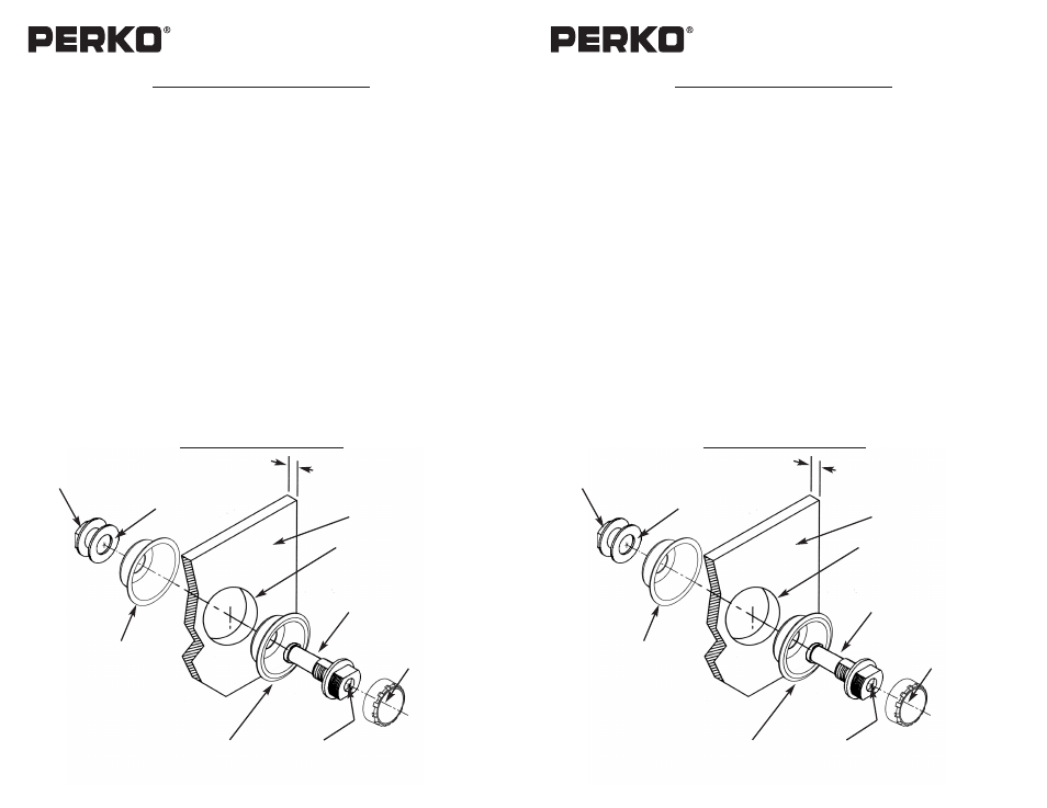
Mounting Diagram
Perko, Inc.
16490 N.W. 13th Ave.
Miami, Fl 33169-5707
www.perko.com
Escutcheon
Vent Body
Hull Mounting Surface
Mounting Flange
Washer
Nut
Drill 1-5/8” Dia. Hole
5/8” Max. Thickness
Screen
Splash Guard
Vent Cap
Cat. Nos. 0597 Series Gas Tank Vent
INSTALLATION INSTRUCTIONS
Read all directions before proceeding.
1). The Tank vent must be installed in accordance with U.S.C.G. Safety
Standards for Boat Gasoline Fuel Systems, #33CFR183 and A.B.Y.C.
Standard H-24.
2). Locate the mounting surface with a thickness up to 5/8 inch maximum.
3). Drill a 1-5/8 inch diameter hole in the mounting surface.
4). Make sure the vent head is tightened against the threaded end of the vent
neck to insure proper seal.
5). Remove nut, washer and mounting flange.
6). Apply bedding compound around the outside of the mounting hole front,
and insert escutcheon and vent body into the mounting hole. Install the
adapter and polymer splash guard vent cap. Tighten securely.
7). Attach the mounting flange, washer and nut. Tighten securely.
8). Attach the vent hose to the barbed end of the vent body, and secure with a
hose clamp.
9). To pressure test the fuel system, remove the splash guard vent cap, and
attach an optional orange test cap (Cat. No. 0101).
10). Remove test cap, and re-attach vent cap after pressure testing.
(1). American Boat & Yacht Council, Inc. (2). U.S. Coast Guard
613 Third Street, Suite 10
Washington, D.C. 20593
Annapolis, MD 21403
(or your local C.G. office)
6/11
0597INS1
Mounting Diagram
Perko, Inc.
16490 N.W. 13th Ave.
Miami, Fl 33169-5707
www.perko.com
Escutcheon
Vent Body
Hull Mounting Surface
Mounting Flange
Washer
Nut
Drill 1-5/8” Dia. Hole
5/8” Max. Thickness
Screen
Splash Guard
Vent Cap