PERKO 9602 User Manual
Diagram #1
Cat No. 9601 Series Basic Switch
Cat No. 9602 Series with Key Lock
Cat No. 9603 Series with Alternator Field Disconnect
Cat No. 9604 Series with Lock and Field Disconnect
BATTERY SWITCHES
INSTALLATION AND OPERATING INSTRUCTIONS
For use with alternators and generators rated 6-32 V.D.C. switch rating: 250 amperes continuous, 360 amperes intermittent.
Locate switch to keep battery cables short as possible.
All wiring to the switch shall be performed by a QUALIFIED MARINE ELECTRICIAN, and in accordance with the “Fire Protection
Standard For Motor Craft”, N.F.P.A.* No. 302, The Standards of the American Boat and Yacht Council, Inc.*, and the U.S.C.G.* Safety
Standards for Boat Electrical Systems (33 CFR 183).
CAUTION:
Always STOP engines before switching to “OFF” position. Erratic operation, particularly after very long periods of
idleness, can be cleared by rapidly switching back and forth briskly several times with out any load connected.
NOTE:
(1) Locate switch to keep battery cables short as possible.
(2) If switch is to be mounted in an area subject to corrosion, it is recommended that a liquid electrical coating be
applied to the terminal connections.
(3) Terminal stud size is 5/16 inch.
(4) Mounting screw size #10 pan head or round head. Do not over-tighten screws to prevent deforming the switch.
OPTIONAL ACCESSORIES
(1) Key Lock - Switch can be locked only in the “OFF” position. Key can be removed in either the locked or unlocked position.
(2) Alternator Field Disconnect - used to break the field current if the battery switch is inadvertently turned to the “OFF” position
with the engine running. Hook-up instructions and applicability are explained in the diagram below
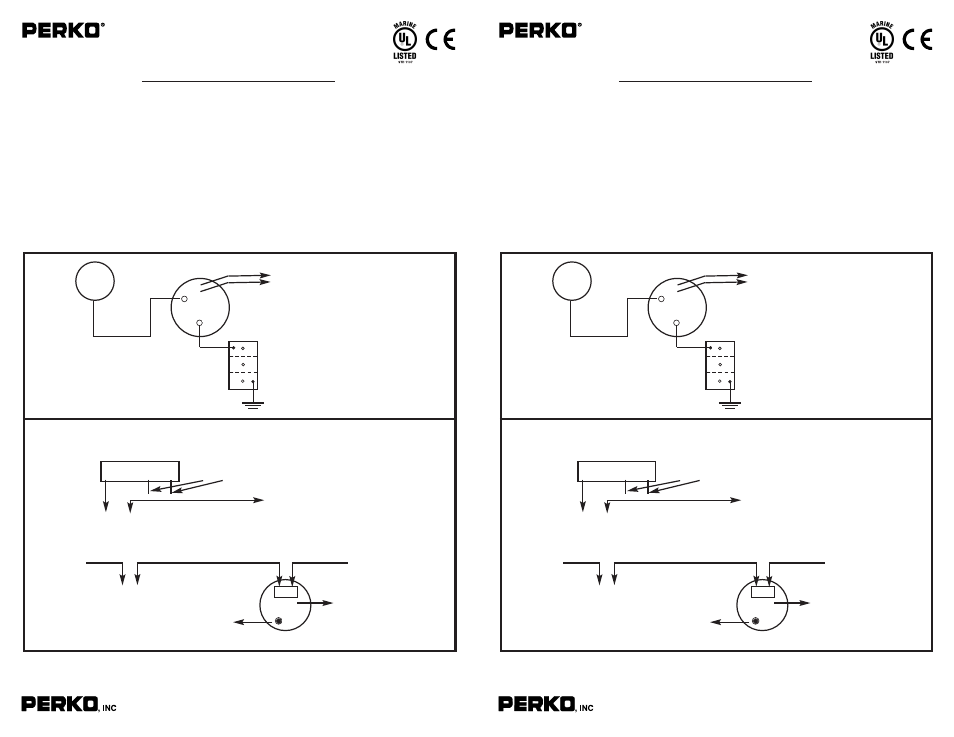
The following diagrams illustrate typical installations.
16490 N.W. 13th Avenue
Miami, Florida 33169-5707
www.perko.com
+
-
F1
•
F2
•
1
COM
Starter
Optional
Alternator Field Disconnect
Terminals F1 & F2
See Diagram #2
DIAGRAM #1
Battery
Engine
Ground
DIAGRAM #2 ALTERNATOR FIELD DISCONNECT
A. Use minimum 14 awg wire, suitable for use in marine engine compartments.
B. On systems with separate regulator, splice the field disconnect switch into the field wire “F” as shown:
1. At the Regulator:
2. On unitized alternators with built-in regulator and 3 wire hook-up, splice the
field disconnect switch into the field wire “F” as shown”
C. On single wire alternators - a field disconnect cannot be installed.
Do Not Disturb “B & A” Wires
To Alternator
F1
F2
To Field Disconnect Switch
Terminals F1 & F2
F R
Alternator
F1
F2
To Field Disconnect Switch
Terminals F1 & F2
Alternator
Output
DO NOT DISTURB
“F & R”
Marked on back of
alternator where
connector plugs in.
Do Not Disturb
“R” Wire
F
B
A
REGULATOR
9/07
9600INS1
1.
American Boat & Yacht Council, Inc.
2.
U.S. Coast Guard
3. N.F.P.A.
613 Third Street, Suite 10
Washington, D.C. 20593
1 Batterymarch Park
Annapolis, MD 21403
(or your local C.G. office)
Quincy, MA 02269
Cat No. 9601 Series Basic Switch
Cat No. 9602 Series with Key Lock
Cat No. 9603 Series with Alternator Field Disconnect
Cat No. 9604 Series with Lock and Field Disconnect
BATTERY SWITCHES
INSTALLATION AND OPERATING INSTRUCTIONS
For use with alternators and generators rated 6-32 V.D.C. switch rating: 250 amperes continuous, 360 amperes intermittent.
Locate switch to keep battery cables short as possible.
All wiring to the switch shall be performed by a QUALIFIED MARINE ELECTRICIAN, and in accordance with the “Fire Protection
Standard For Motor Craft”, N.F.P.A.* No. 302, The Standards of the American Boat and Yacht Council, Inc.*, and the U.S.C.G.* Safety
Standards for Boat Electrical Systems (33 CFR 183).
CAUTION:
Always STOP engines before switching to “OFF” position. Erratic operation, particularly after very long periods of
idleness, can be cleared by rapidly switching back and forth briskly several times with out any load connected.
NOTE:
(1) Locate switch to keep battery cables short as possible.
(2) If switch is to be mounted in an area subject to corrosion, it is recommended that a liquid electrical coating be
applied to the terminal connections.
(3) Terminal stud size is 5/16 inch.
(4) Mounting screw size #10 pan head or round head. Do not over-tighten screws to prevent deforming the switch.
OPTIONAL ACCESSORIES
(1) Key Lock - Switch can be locked only in the “OFF” position. Key can be removed in either the locked or unlocked position.
(2) Alternator Field Disconnect - used to break the field current if the battery switch is inadvertently turned to the “OFF” position
with the engine running. Hook-up instructions and applicability are explained in the diagram below
The following diagrams illustrate typical installations.
16490 N.W. 13th Avenue
Miami, Florida 33169-5707
www.perko.com
+
-
F1
•
F2
•
1
COM
Starter
Optional
Alternator Field Disconnect
Terminals F1 & F2
See Diagram #2
DIAGRAM #1
Battery
Engine
Ground
DIAGRAM #2 ALTERNATOR FIELD DISCONNECT
A. Use minimum 14 awg wire, suitable for use in marine engine compartments.
B. On systems with separate regulator, splice the field disconnect switch into the field wire “F” as shown:
1. At the Regulator:
2. On unitized alternators with built-in regulator and 3 wire hook-up, splice the
field disconnect switch into the field wire “F” as shown”
C. On single wire alternators - a field disconnect cannot be installed.
Do Not Disturb “B & A” Wires
To Alternator
F1
F2
To Field Disconnect Switch
Terminals F1 & F2
F R
Alternator
F1
F2
To Field Disconnect Switch
Terminals F1 & F2
Alternator
Output
DO NOT DISTURB
“F & R”
Marked on back of
alternator where
connector plugs in.
Do Not Disturb
“R” Wire
F
B
A
REGULATOR
9/07
9600INS1
1.
American Boat & Yacht Council, Inc.
2.
U.S. Coast Guard
3. N.F.P.A.
613 Third Street, Suite 10
Washington, D.C. 20593
1 Batterymarch Park
Annapolis, MD 21403
(or your local C.G. office)
Quincy, MA 02269