Demonstration 3: diamagnetism and paramagnetism, Introduction, Setup – PASCO EM-8642A Magnetic Force Accessory User Manual
Page 11: Procedure
®
E M - 8 6 4 4 B
0 1 2 -1 2 7 2 2 A
D e m o n s t r a t i o n 3 : D i a m a g n e t i s m a n d
7
Demonstration 3: Diamagnetism and Paramagnetism
Introduction
Compared to ferromagnetism, diamagnetism and paramagnetism are weak effects. However, when a diamagnetic
material is placed in a strong magnetic field, it is possible to see that the material is repelled by the magnetic field.
On the other hand, if a paramagnetic material is placed in a strong magnetic field, it will be noticeably attracted to
the magnetic field and will align itself with the field.
Setup
1.
Tie pieces of thread (included with the Magnetic Force
Accessory) around the middle of the glass rod and the
aluminum tube. Secure the thread in place with a small
piece of tape to prevent the sample from slipping out of
the thread loop.
2.
Use the adjustment screws to expand the gap of the
Variable Gap Magnet until the gap is about 3.8 cm
(1.5”) or slightly larger than the length of the glass rod
and aluminum tube.
3.
Hang the glass rod from the mounting bar so that the
rod is at the same level as the Variable Gap Magnet
when the magnet is placed on its side.
4.
For large class viewing, put the magnet and the large
base on an overhead projector and focus the projector
on the glass rod. The mounting bar will not obstruct the
view because it will be out of focus.
Procedure
1.
For the glass rod, show that when you place the rod parallel to the magnetic field lines, the rod rotates and
oscillates about an equilibrium position which is perpendicular to the magnetic field lines of the magnet.
Eventually the glass rod will come to rest in this equilibrium position but it takes longer than you will want
to wait. Instead, use you hand to stop the glass rod in the equilibrium position (perpendicular to the field).
Then, to show that the rod is held in position by the magnetic field, slowly rotate the magnet about the axis
formed by the thread. The glass rod will rotate, always staying perpendicular to the magnetic field lines.
2.
Follow the same procedure for the aluminum tube (the paramagnetic sample). However, instead of initially
aligning it parallel to the magnetic field lines, put the aluminum tube perpendicular to the field to show that
it will rotate into an equilibrium position that is parallel to the magnetic field lines. When the aluminum tube
Equipment Needed
Equipment Needed
Variable Gap Magnet (EM-8618)
Large Base and Rod (ME-9355)
Magnetic Force Accessory (EM-8642A)
Tape
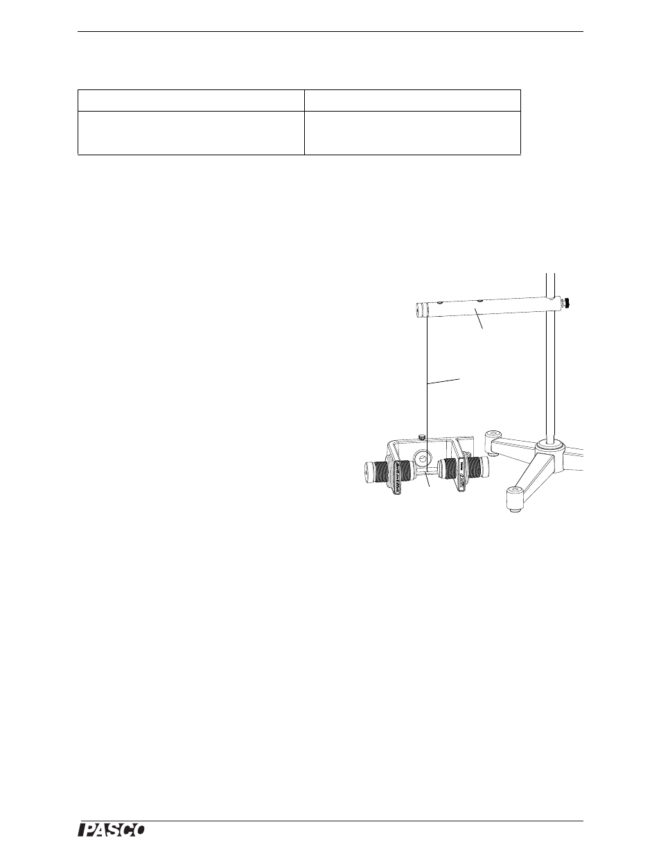
Figure: Demo Setup
Glass rod
Thread
Mounting rod