Daisy-chained output shut-down, Analog programming of output voltage and current – Agilent Technologies N5700 User Manual
Page 44
Analog Programming of Output Voltage and Current
44
Series N5700 User’s Guide
In Auto-Restart mode, the power supply restores the operating
settings that were saved when it was last turned off (see below). The
output is either enabled or disabled according to its last setting.
Output On/Off state
UVL level
Output voltage setting
OCP setting
Output current setting
Locked/Unlocked front panel
OVP level
Start-up mode
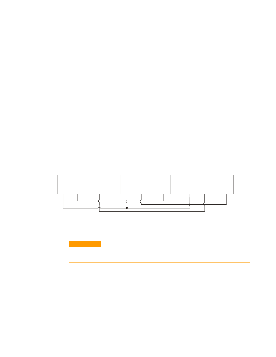
Daisy-Chained Output Shut-down
It is possible to configure a multiple power supply system to shut
down all the units when a fault condition occurs in one of the units.
SW1 setup switch 5 must be in the Down position to enable the daisy-
chain operation. Other switches are unaffected by this setting.
If a fault occurs in one unit, its Power Supply OK signal is set low and
its display will indicate the fault. The other units shut off with their
displays indicating SO. When the fault condition is cleared, all units
will recover according to their Safe-Start or Auto-Restart settings.
The following figure shows three units daisy-chained - the same
connection method can be used with additional units. The Shut Off
and Power Supply OK signals are referenced to Chassis Common (J1
pins 2 and 3).
Analog Programming of Output Voltage and Current
CAUTION
J1 pin 12, pin 22, and pin 23 are internally connected to the negative sense
terminal. Do not reference these pins to any terminal other than the negative
sense terminal, as it may damage the unit.
In Local mode, the output voltage and current is programmed with
the front panel VOLTAGE and CURRENT knobs or over the remote
interface. In Analog mode, the output voltage and current can be
programmed either by an analog voltage or by resistors connected to
the rear panel J1 connector.
The J1 connector also provides monitoring signals for the output
voltage and output current. The programming range and monitoring
signal range can be selected using the SW1 setup switch.
POWER SUPPLY
#
1
J1-2,3 J1-16
J1-16
J1-16
J1-15
Supply OK
POWER SUPPLY
#
2
J1-2,3
J1-15
POWER SUPPLY
#3
J1-2,3
J1-15
Shut Off
Com
Shut Off
Supply OK
Com
Com
Supply OK
Shut Off