Basic specifications suggestions, Technical support, Trigger in-out – PASCO PS-2190 1 MHz 2-channel Voltage Sensor User Manual
Page 4
®
1 M H z 2 - c h a n n e l V o l t a g e S e n s o r
PS-2190
4
Trigger In-Out
The PS-2190 has two BNC connectors on the rear panel labeled
Trigger In and Trigger Out. By connecting the Trigger Out of one
PS-2190 to the Trigger In of a second PS-2190, the two sensors
are time synchronized and four channels can be measured. Since
the Xplorer GLX can currently only display two channels in
Scope Mode, this feature is for future use.
Basic Specifications
Suggestions
•
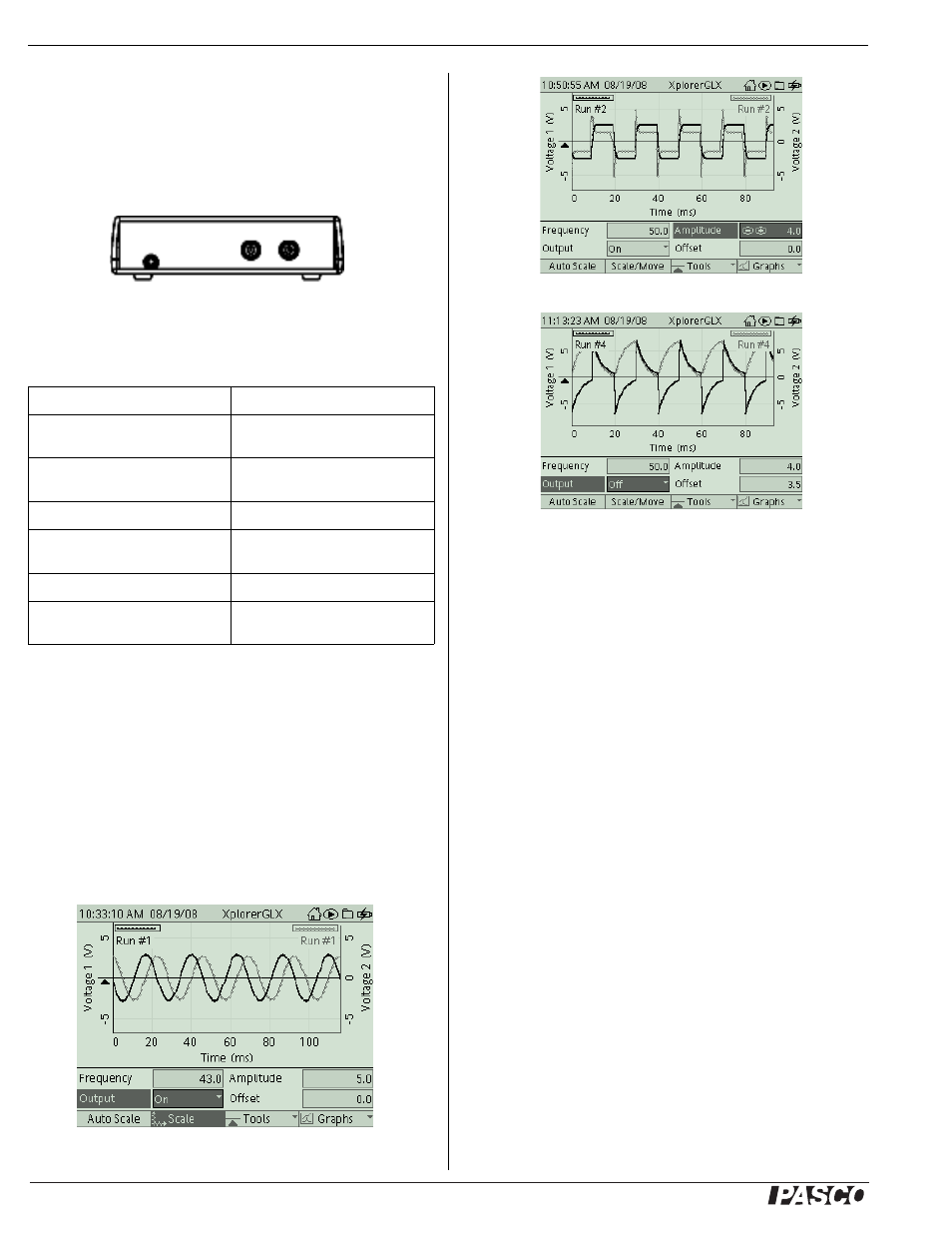
Measure the voltage of a resistor-inductor-capacitor (RLC)
circuit as an input AC voltage sine waveform ranges from
below resonant frequency to above resonant frequency.
•
Measure the voltage of a resistor-inductor (RL) circuit with
an input AC voltage square waveform at 50 Hz.
•
Measure the voltage of a resistor-capacitor (RC) circuit as
the capacitor charges and discharges through the resistor.
RLC Circuit
RL Circuit
RC Circuit
Technical Support
For assistance with any PASCO product, contact PASCO at:
For more information about the 1 MHz 2-channel Voltage Sensor
and the latest revision of this Instruction Sheet, visit:
www.pasco.com/go?PS-2190
Limited Warranty
For a description of the product warranty, see the
PASCO catalog.
Copyright
The PASCO scientific 012-10253A 1 MHz
2-channel Voltage Sensor Instruction Sheet is copyrighted with all rights
reserved. Permission is granted to non-profit educational institutions for
reproduction of any part of this manual, providing the reproductions are
used only in their laboratories and classrooms, and are not sold for profit.
Reproduction under any other circumstances, without the written consent
of PASCO scientific, is prohibited.
Trademarks
PASCO, PASCO scien-
tific, DataStudio, and PASPORT are trademarks or registered trademarks
of PASCO scientific, in the United States and/or in other countries. All
other brands, products, or service names are or may be trademarks or
service marks of, and are used to identify, products or services of, their
respective owners. For more information visit www.pasco.com/legal.
Channels
two, differential
Maximum Sample Rate (Burst
Mode)
1 million samples per second
Maximum Sample Rate
(Continuous Mode)
20,000 sample per second
Input Voltage Ranges
±10 V, ± 1 V, ± 0.1 V full scale
Resolution
12-bit analog-to-digital converter,
5 mV at ±10 volts
Analog Bandwidth
120 kiloHz (-1 dB) typical
Absolute Maximum Input
Voltage Without Damage
45 volts
Figure 8: Rear Panel
Address: PASCO scientific
10101 Foothills Blvd.
Roseville, CA 95747-7100
Phone:
+1 916-786-3800
(worldwide)
800-772-8700 (U.S.)
Fax:
(916) 786-7565
Web:
www.pasco.com
E-mail: