Manual release adjustment, Manual release assembly – Dings Dynamics Group 1-70 Series180TC - 250TC User Manual
Page 7
Manual Release Adjustment
CAUTION: Load to be removed or blocked. Brake will be
inoperative during this procedure.
The manual release (3) may require adjustment after
replacing the operator assembly 15), magnet (15A0, or
armature (15J). It also may be required if adjustments are
made on the pivot stud nuts (19).
The release is working properly if:
a) you turn release knob (3) clockwise to stop and the
brake is released;
b) the release knob returns to its normal position
automatically when power is applied to the magnet.
NOTE: Cover (20) must be removed to make this adjustment.
1. To adjust: Set air gap “A” as described under “Wear
Adjustment” on page 4.
2. If the brake does not release, turn adjusting screw
(5) counterclockwise 1/4 turn and try again.
3. If the release knob (3) does not return to its normal
position automatically, turn screw (5) clockwise 1/4
turn and try again.
NOTE: You may have to repeat Steps 2 or 3 to get
the release to operate properly.
It is important that the release knob returns to its
normal position automatically when power is applied
to the magnet.
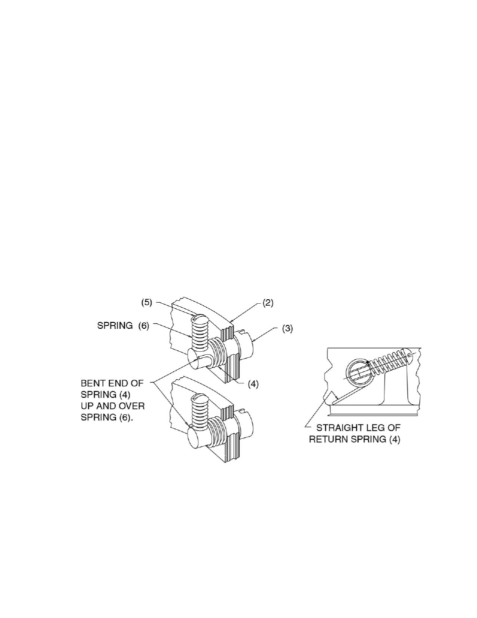
Manual Release Assembly
Refer to Fig. 6
1. Place shaft of release knob (3) through hole in
bracket (2).
2. Slide return spring (4) over shaft; straight leg of
spring should enter shaft first with leg in the position
shown.
3. Slip spring (6) over screw (5) and install in tapped
hole in release shaft. Screw in until it stops.
Make sure spring (4) is not caught under spring (6).
4. Engage bent end of spring (4) over spring (6) as
shown. Pull it over with a needle-nose pliers or
screwdriver.
5. Adjust release. See “Manual Release Adjustment” on
the left.
Figure 6
7