Backlight, Power, Backlight power – Liquid Controls Sponsler IT400 Electronic Register User Manual
Page 16
Liquid Controls
Sponsler, Inc.
IT400 Remote Totalizer & Rate Indicator
Page: 13
DOC#: MN-IT400-R2d.doc
• Signal
Sinusoidal signal: low amplitude crossing signal that doesn’t exceed the IT400’s input
specification. This signal can come directly from the pickup coil sensing rotation of the
attached Sponsler, Inc. turbine flowmeter or other flowmeter device.
input from practically any frequency generating device producing a sinusoidal signal, a
square wave pulse or can be connected to a modulated carrier pickup coil.
Square signal: any zero referenced pulse that doesn’t exceed the IT400’s input
specification.
Modulated carrier: derived by modulating a carrier signal of the pickup coil caused by
the change in impedance resulting from the rotor blades passing in proximity to the coil.
This is an inductive coil therefore there is no drag on the rotor. MC coil operation is
factory enabled only. MC coil operation requires DC or loop power.
Note: SW5-3 must be “On” for MC coil operation when externally DC powered.
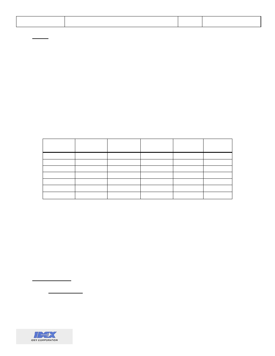
Backlight
The backlight is controlled by a combination of system parameters. The following table lists the
operation of the backlight and how it is controlled by these various system parameters:
DC
Powered
4-20mA
Powered*
Battery
Condition
BLI TE
value
Backlight
in - RUN-
Backlight
in Menu
Yes
Don’t Care
Don’t Care
Non-Zero
ON
ON
No
No
Good
Non-Zero
Timer
ON
No
No
Low
Don’t Care
Manual
OFF
No
Yes**
Good
Non-Zero
Timer
ON
No
Yes
Don’t Care
Don’t Care
Manual
OFF
Don’t Care
Don’t Care
Don’t Care
DI SABLED
Manual
OFF
Don’t Care
No
Good
ALWAYSoN
ON
ON
* SW5-1, SW5-2, & SW5-3 “On”.
** SW5-3 “Off” (4-20mA loop to power modulated input and battery to power main circuit).
*** If the timer is set to ALWAYSoN, the battery will last about two months when not DC powered.
The front panel magnetic reed switch activates the backlight regardless of anything (as long as power
is applied). Backlight activation may increment one additional input pulse and will cause 4-20mA
errors.
Power
The IT400 may be powered externally by any 5-48VDC source, 4-20mA loop, internally by battery, or
by a combination of these. Power consumption is affected by programmed options, input signal
frequency, and the programmed power mode.
•
o
DC: 5-48VDC
External Power
o
4-20mA Loop: used to power the IT400 or just the modulated carrier circuit (which
requires more voltage than is available from the battery). The IT400 requires 7VDC of
the loop supply.