Wiring the lcr – Liquid Controls LCR Install User Manual
Page 13
13
Wiring the LCR
Installing factory-supplied printer Power cable, LCR
Power Cable, and printer data cable
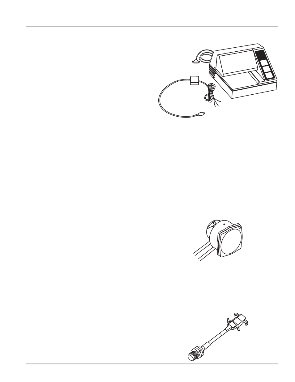
Your LCR includes an electrical black-sheathed10-
conductor printer data cable for connecting the LCR at
the rear of the vehicle to the printer located in the vehicle
cab, and a separate gray-sheathed 3-wire power cable
for connecting the LCR to the accessory circuit in the
vehicle cab. For your convenience, the cables have been
factory pre-wired to the LCR, and are ready for routing
to the vehicle cab. The cable assemblies should be run
in 3/4” automotive black plastic corrugated split loom to
protect the cables from the elements. Make sure the
loom is securely fastened to the truck. NOTE: Be
especially careful to keep the cables away from hot
surfaces, rotating shafts, and moving linkages.
Printer Data Cable (P/N 81513040)
Connect the D-connector on the free end of the black
printer data cable to the receptacle on the back of the
printer in the vehicle cab. NOTE: The socket labeled
“KD”(telephone style connector) on the back of the printer
is NOT used. Printer may be located a maximum of 50
feet from LCR.
Printer Power Cable (24 VDC)
Printer power is supplied through the socket labeled “24
VDC” on the back of the printer. The 82500 DC/DC
converter plugs into this socket. The pigtail end of the
82500 must be connected to the accessory circuit (red)
to 12 VDC and (black) to system ground. See page 14.
LCR Power Cable (P/N 81512)
Connect the black lead of the power cable for the LCR to
a suitable grounding point in the cab. Connect the red
lead to a source of 12 VDC power that is on the vehicle
“accessory” circuit (the LCR is designed to be “OFF”
when the vehicle is turned off). Typically the ignition
switch and the fuse panel are sources of 12-volt power.
If power is drawn from a fuse tap, make sure the cable
connection is on the load side of the fuse. The power to
the LCR should be “OFF” when the truck ignition switch
is in the “OFF” position. NOTE: The LCR Power Cable
Kit includes a 5 Amp fuse holder and fuse to protect the
truck system in the event of a short circuit in the cable.
Liquid Controls recommends that this fuse be used in all
installations not having a fused accessory panel already
in the truck. See page 14. A 5 Amp fuse is required.
CAUTION
: Electrical Power must be off until all wiring
operations have been completed.
Wiring the pod pulser to lcr (optional)
LCR is most commonly supplied with an internal pulser
for the convenience of the customer. In such cases, the
optional external POD pulser is not used. If the LCR is
located remotely from the meter, the POD pulser is
required to supply pulse outputs to the LCR.
The POD pulser should be installed in accordance with
the installation instructions supplied with the POD (Series
E200 Installation, and Operation Manual). Wire the POD
to terminal block J8, Pins 31, 33, 34, and 37, as shown
on page 15. Route wires from the POD into the LCR
through Port 6.
NOTE: For connection of other design pulsers, refer to
page 19 of this manual.
Wiring odometer PULSER to lcr (optional)
The Odometer pulser is mechanically installed on the
vehicle in accordance with the installation manual
provided with the odometer kit. The 3-wire cable from
the odometer pulser is wired to terminal block J8, Pins
31, 36, and 38, as shown on page 15. Route wires from
the odometer pulser into the LCR through Port 6.