Wiring the lcr – Liquid Controls LCR Install User Manual
Page 12
12
Wiring the LCR
Wiring of Valve Solenoids to LCR
When wiring valve solenoids to the LCR, the wires may
have to be spliced in order to reach the appropriate
terminal strip location. Use stranded 18 GA wire. It is
recommended that red wire be used for the main
connections, though black can be used as a substitute.
Green 18 GA stranded wire should be used for the
solenoid case ground. Leave a small amount of excess
wire to allow for future servicing of the junction box wiring.
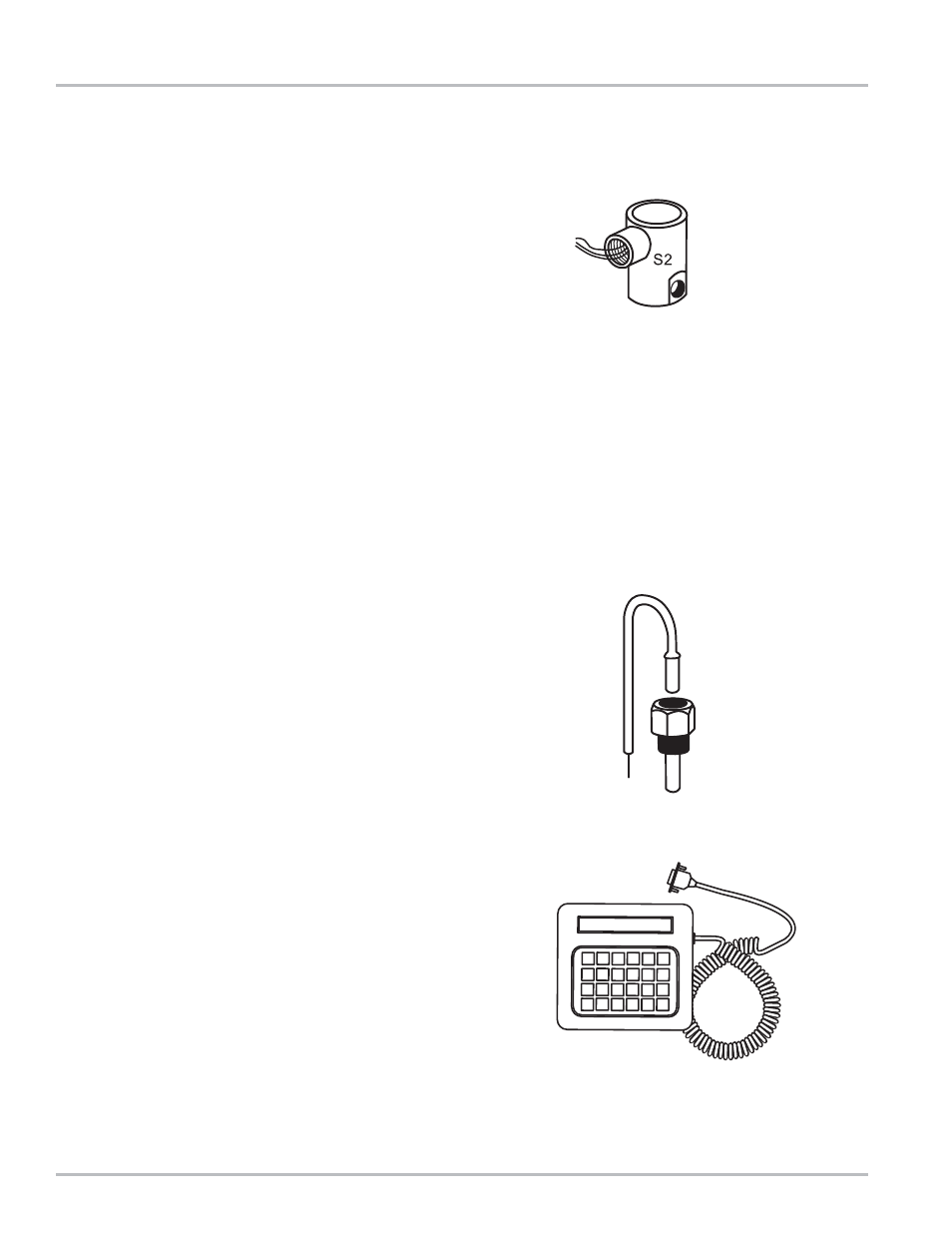
Single-Stage Valve and Three-Way Solenoid Wiring
Single-stage (security) valve solenoid (S2) or three-way
solenoid (LPG service) should be wired into terminal block
J13, Pins 17, 18, and 19, as shown on page 14. Solenoid
operates when the LCR pulls SOL-2 (Pin 18) signal low.
Two-Stage Valve Solenoid Wiring
The S1 and S2 solenoids are connected to terminal block
J13, Pins 14, 15, 16, and 17, 18, and 19, respectively, as
shown on page 14. The SOL-1 signal is connected to
the bonnet solenoid (S1). The SOL-2 signal is connected
to the bypass solenoid (S2). Each solenoid will be turned
on when the LCR pulls its respective signal low (SOL-1;
SOL-2).
Wiring RTD Temperature Probe to LCR (Optional)
Make sure that there is enough slack in the conduit
leading from the LCR to the strainer mounted RTD to
allow the strainer cover to be removed. Feed the cable
from the back of the RTD through the conduit to the LCR.
Cut the cable on the LCR end, leaving enough to expose
a few inches of the wires inside. Strip the insulation from
the wires and connect them to terminal block J14, Pins
20, 21, 22, and 23, as shown on page 14. The two white
wires are connected to Pins 20 and 21, and the two red
wires to Pins 22 and 23.
Connecting Lap Pad to LCR (optional)
The optional Liquid Controls Lap Pad is connected to
the printer in the cab of the truck. Each Lap Pad is
provided with a 3-terminal Lap Pad Adapter that provides
a junction for the Lap Pad, the printer, and the LCR printer
cable. The Lap Pad adapter is inserted in the port at the
back of the printer. Then, the printer cable from the LCR
is installed in the back of the adapter. Refer to page 14.
NOTE
: The jumper on terminal J10 on LCR circuit board
must be in the RS-232 position for operation of the Lap
Pad (factory set position). See page 14.