Montaje/instalación, Assembly/installation – Level Mount PT900 User Manual
Page 7
38
www.levelmount.com
1-888-229-1459
EU: +0044 844 567 2657
UK: 0844 567 2657
©2011 Level Mount - Patents Pending
Montaje/Instalación
Imagen 11
Nivel de burbuja
incorporado/Nivel
Imagen 8
Pladur con estructuras visibles
Detector
de Madera
Imagen 9
Estructura
de Pladur
Imagen 10
Llave hexagonal
Arandelas
a
as
s
s
Tornillo
hexagonal
Estructura
de Pladur
Paso 4 – Fijar la placa de soporte a la pared
Opción A – Si las paredes son de pladur
Para fijar la placa de soporte a una pared de pladur, localice las estructuras de
madera con un detector de madera. Cuando haya encontrado el lugar donde crea
que está el centro de la estructura de madera (utilizando el Detector de Madera),
clave un clavito en el hueco lo suficiente para confirmar que está clavando sobre
madera sólida (y no en algo menos denso, como una tabla de aglomerado); una
vez realizado, vuelva a quitar el clavito.
Alinee el agujero superior izquierdo de la Placa de soporte con el centro de la
estructura de madera que haya marcado en la pared, a la altura deseada. Utilice
un lápiz para marcar la pared a través del agujero superior izquierdo de la Placa
de soporte sobre el centro de la estructura, tal y como muestra la Imagen 9.
Para fijar la Placa de soporte a la pared, taladre un agujero guía de 4 mm sobre
el lugar marcado con el lápiz. Utilizando la llave hexagonal, atornille 1 tornillo
hexagonal con arandela (Bolsa 6) por el agujero superior izquierdo de la Placa de
soporte, atravesando la pared de pladur hasta llegar a la estructura de madera, tal
y como muestra la Imagen 10.
Una vez fijado el tornillo superior izquierdo, ajuste la Placa de Soporte usando
el Nivel de burbuja que viene incorporado o el nivel, hasta que la Placa esté
nivelada, tal y como muestra la Imagen 11. Marque con un lápiz los 3 agujeros
restantes. Taladre los 3 agujeros que acaba de marcar con una broca de 4 mm.
Utilizando la llave hexagonal, atornille los otros 3 tornillos hexagonales con
arandelas (Bolsa 6) para fijar la Placa de soporte a la pared, tal y como muestra la
Imagen 12. Atornille bien, hasta que quede fijo, pero con cuidado de no pasarse
de rosca, pues de lo contrario podría dañar el soporte o los tornillos.
Cuidado:
Debido al peso del televisor de pantalla plana, es fundamental
montar la Placa de soporte en al menos 2 estructuras de
madera, y que utilice los 4 tornillos para fijar la Placa a la pared.
Imagen 12
Estructura
de Pladur
Arandelas
Tornillo
hexagonal
Placa de soporte
Placa de soporte
Arandelas
Llave
hexagonal
Placa de soporte
Placa de soporte
Placa de soporte
Placa de soporte
Placa de soporte
Placa de soporte
7
www.levelmount.com
1-888-229-1459
EU: +0044 844 567 2657
UK: 0844 567 2657
©2011 Level Mount - Patents Pending
Assembly/Installation
Step 1 – Selecting the Correct Hardware Based on TV
Back
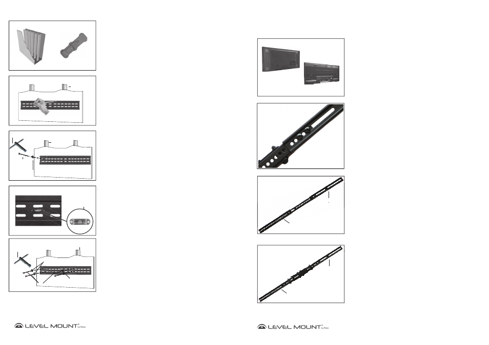
Before beginning the installation, determine if the TV has a flat back or a
recessed back as shown in Figure 1. If you have a recessed back TV you may
need to use the spacers (Bag 5) as shown in Figures 4 and 6. The spacer
is used to fill the recessed area of the TV so that the TV Bracket is fully
supported and flush with the back of the TV.
Flat Back
Recessed Back
Figure 1
Step 2 - Extension Arm Installation (if needed)
If the holes on the Fixed Arms do not line up with the holes in back of the
TV, do not drill. Instead, follow these instructions for the Extension Arm
Installation. Otherwise, skip to Step 3.
Note: Extension arms are not needed for Flat Panel TVs that fit the 200 or
400 Series TV Wall Mounts. This extension can be used for 600 or
900 Series TV Wall Mounts that fit Flat Panel TVs with a VESA vertical
hole placement that is greater than 370mm for Fixed Arms or greater
than 500mm for Tilt Arms. Your TV manual/product labels should
specify the VESA hole spacing.
Step 2a - Attaching Extension Arms to Fixed or Tilt Arms
-
please note extension arms are only included in the 600 and 900
Series
Attach the Extension Arms to the Fixed or Tilt Arms using the following hardware
as shown in Figure 2:
• Bolts M8 (Bag 7)
• Lock Washer M8 (Bag 7)
• Extension
Arm
• Fixed or Tilt Arm
• Hex Nut M8 (Bag 7)
Adjust the bolt in Figure 2 to move the extension arms to align with the holes on
the back of the Flat Panel TV.
Step 2b - Completed Extension Arm Attachment
All 4 Extension Arms should be attached in the same manner. When completed,
your Fixed or Tilt Arms with the Extension Arms attached, should appear as
shown in Figure 3A or 3B.
Figure 3A
Upper
Extension Arm
Lower
Extension Arm
Figure 2
Figure 3B
Figure 2
S
Upper
Extension Arm
pp
p
Lo
Upper
Extension Arm
Lower
Extension Arm
Fixed Arm
Tilt Arm