Assembly/installation, Montaje/instalación – Level Mount PT900 User Manual
Page 10
10
www.levelmount.com
1-888-229-1459
EU: +0044 844 567 2657
UK: 0844 567 2657
©2011 Level Mount - Patents Pending
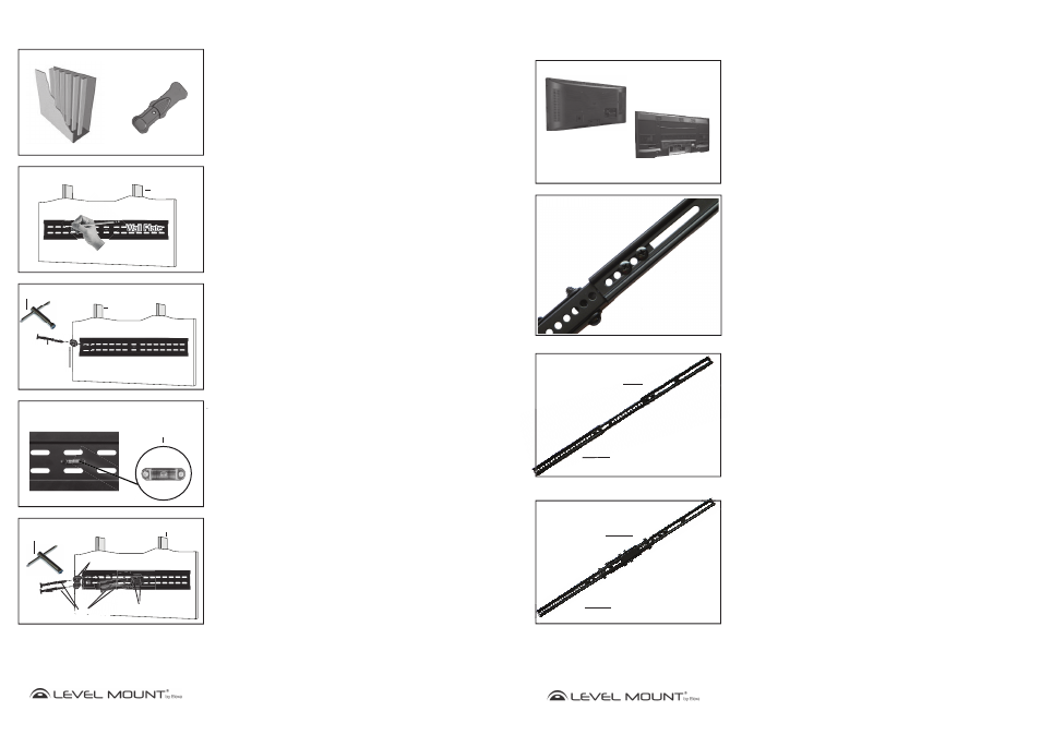
Assembly/Installation
Figure 11
Built-in Bubble Level/
Spirit Level
Wall Plate
Wall Plate
Figure 8
Drywall with Exposed Studs
Stud Finder
Figure 9
Wall Plate
Drywall Stud
Wall Plate
Wall Plate
Figure 10
Hex Nut Wrench
Washer
a
ash
h
h
h
h
h
Hex
Screw
Wall Plate
Wall Plate
Drywall Stud
Step 4 - Attaching the Wall Plate to the Wall
Option A – If the Wall is Drywall
To attach the Wall Plate to drywall, locate the wooden studs with the enclosed
Stud Finder as shown in Figure 8 and as shown in the Stud Finder Instructions
(included in this document). After you have determined the spot where you
believe the center of the stud to be (using the Stud Finder), hammer a small
nail into that spot far enough to confirm that you are hammering into solid
wood (and not something less dense, like particle board), then remove the nail
when done.
Line up the left top hole of the Wall Plate with the stud center marked on the
wall at the desired height. Then, use a pencil to mark the wall through the top
left hole in the Wall Plate over the center of one of the studs as shown in Figure
9
To attach the Wall Plate to the wall, drill a 4mm pilot hole where the top left
pencil mark was made. Using the Hex Nut Wrench, drive 1 Hex Screw with
Washer (Bag 6) through the top left slot in the Wall Plate and through the
drywall into the stud as shown in Figure 10.
Once the top left screw is secure, adjust the Wall Plate until it is level using the
Built-in Bubble Level/Spirit Level as shown in Figure 11. With a pencil mark
the 3 remaining holes. Drill the 3 remaining holes with a 3mm drill bit where
marked.
Using the Hex Nut Wrench, drive in the additional 3 Hex Screws and Washers
(Bag 6) to secure the Wall Plate to the wall as shown in Figure 12. Screw
tightly enough to produce a strong bond, but do not over-tighten or there may
be damage to the mount or screws.
Caution: Due to the weight of the Flat Panel TV it is essential to mount the Wall
Plate to at least 2 wooden studs and that all 4 screws be used when
mounting the Wall Plate to the wall.
Figure 12
Hex Nut Wrench
Wall Plate
Wall Plate
Washer
Washer
Washer
Hex Screw
Drywall Stud
x
x
re
x
x
S
cr w
r w
x
x
S
Screw
x
x
x
Sc
Sc
c w
x
x
x
S
S
S
S
Sc
S
Screw
35
www.levelmount.com
1-888-229-1459
EU: +0044 844 567 2657
UK: 0844 567 2657
©2011 Level Mount - Patents Pending
Brazos de
extensión
superiores
Brazos de
extensión
inferiores
Brazo fijo
Montaje/Instalación
Paso 1 – Escoja el soporte correcto en función de la parte
trasera de su televisor
Antes de empezar la instalación, compruebe si la parte trasera de su televisor es
plana o hueca, tal y como muestra la Imagen 1. Si la parte trasera de su televi-
sor es hueca, es posible que necesita utilizar los separadores (Bolsa 5), tal y como
muestran las Imágenes 4 y 6. Los separadores sirven para rellenar el hueco que
queda en la parte trasera de su televisor, de manera que el soporte quede perfecta-
mente fijado a la parte trasera de su televisor.
Respaldo plano
Respaldo hueco
Imagen 1
Paso 2 – Instalación del Brazo de Extensión (en caso necesario)
Si los agujeros del brazo de extensión no están alineados con los agujeros de la
parte trasera de su televisor, no taladre ningún otro agujero. En lugar de ello, siga
estas instrucciones para instalar el brazo de extensión. En caso contrario, vaya
directamente al Paso 3.
Nota:
Los televisores de pantalla plana adecuados para los soportes de pared
Modelo 200 o 400 no necesitan brazos de extensión. Puede utilizar los brazos de
extensión para los Modelos 600 o 900, adecuados para televisores de pantalla plana
con modelo VESA de agujero vertical mayor de 370 mm para Brazos Fijos o mayor
de 500 mm para Brazos Giratorios o Voladizos. Las instrucciones o etiquetas de su
televisor deberían especificar el tipo de modelo VESA de agujeros de su televisor.
Paso 2a – Fijar el Brazo de Extensión a los Brazos Fijos o
Giratorios –
por favor, tenga en cuenta que los brazos de extensión se
incluyen sólo en los modelos 600 y 900
Fije el Brazo de Extensión a los Brazos Fijos o Giratorios utilizándolas siguientes her-
ramientas, tal y como muestra la Imagen 2:
•
Tornillos M5 (Bolsa 7)
•
Arandelas de presión M5 (Bolsa 7)
• Brazo
de
extensión
•
Brazo fijo o giratorio
•
Tuerca hexagonal M5 (Bolsa 7)
Ajuste el tornillo de la Imagen 2 para mover los brazos de extensión de manera que
queden alineados con los agujeros de la parte trasera de su televisor de pantalla
plana.
Paso 2b – Fijación completa del Brazo de Extensión
Los 4 Brazos de Extensión deberían estar fijados de la misma forma. Una vez termi-
nado, sus brazos fijos o giratorios junto con los brazos de extensión deberían tener el
aspecto de las Imágenes 3A o 3B.
Brazos de
extensión
superiores
Brazos de
extensión
inferiores
Brazos
giratorio
Imagen 3B
Imagen 2
Imagen 3A
Imagen 2
ón
superiores
Brazo
•