Presetting an output port, Writing the outputs, Port c – Impulse PIO-48.PC104 (3701) User Manual
Page 14: Register description
© Sealevel Systems, Inc.
- 12 -
PIO-48.PC104 User Manual
Presetting an Output Port
Each port has an output register associated with it. This register may be written and
retains its value whether the port is configured as an input or an output. To preset the
value of an output port the program should write to the port when it is configured as
an input then configure it as an output.
Writing the Outputs
The outputs are active high. Writing a one (1) corresponds to 5V while writing a
zero (0) corresponds to 0V, at the output.
Port C
Port C is written and read to as two four bit ports. If both lower and upper nibbles
are configure the same then no special considerations need to be made. But if they
are configured differently, one nibble as input, and one as output then the user will
have to keep this in mind. When reading, the input will be returned on the
corresponding upper or lower nibble while the current outputs will be returned on
their corresponding upper or lower nibble. When writing, the corresponding nibble
will be written to the output nibble, while the input nibble will have its output
register written to. The output register can be written to without affecting the inputs.
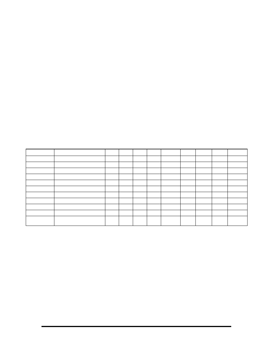
Register Description
Address
Mode
D7
D6
D5
D4
D3
D2
D1
D0
Base+0
Port A1
RD/WR PA1D7 PA1D6 PA1D5
PA1D4
PA1D3 PA1D2 PA1D1
PA1D0
Base+1
Port B1
RD/WR PB1D7 PB1D6 PB1D5
PB1D4
PB1D3 PB1D2 PB1D1
PB1D0
Base+2
Port C1
RD/WR PC1D7 PC1D6 PC1D5
PC1D4
PC1D3 PC1D2 PC1D1
PC1D0
Base+3
Control Word Port 1
WR
0
0
0
CW1D4 CW1D3
0
CW1D1
CW1D0
Base+4
Interrupt config Port 1
RD/WR
0
0
0
0
0
IRQEN1 IRQC11
IRQC10
Base+5
Interrupt status Port 1 and 2
RD
0
0
0
IRQST2
0
0
0
IRQST1
Base+8
Port A2
RD/WR PA2D7 PA2D6 PA2D5
PA2D4
PA2D3 PA2D2 PA2D1
PA2D0
Base+9
Port B2
RD/WR PB2D7 PB2D6 PB2D5
PB2D4
PB2D3 PB2D2 PB2D1
PB2D0
Base+A (10)
Port C2
RD/WR PC2D7 PC2D6 PC2D5
PC2D4
PC2D3 PC2D2 PC2D1
PC2D0
Base+B (11)
Control Word Port 2
WR
0
0
0
CW2D4 CW2D3
0
CW2D1
CW2D0
Base+C (12)
Interrupt config Port 2
RD/WR
0 0 0 0 0
IRQEN2
IRQC21
IRQC20