Programming the pio-48.pc104 – Impulse PIO-48.PC104 (3701) User Manual
Page 12
© Sealevel Systems, Inc.
- 10 -
PIO-48.PC104 User Manual
Physical Connection
The port signals for the PIO-48.PC104 are physically connected via two 50-pin box
headers. P5 provides the connections for ports A1-C1 and P2 provide the
connections for A2-C2. These headers are compatible with the industry standard 50-
pin ribbon/IDC type cabling. This allows for a direct cabling connection between the
PIO-48.PC104 and a Solid State Relay Rack (i.e. PB-8. PB-16, PB-24 etc.)
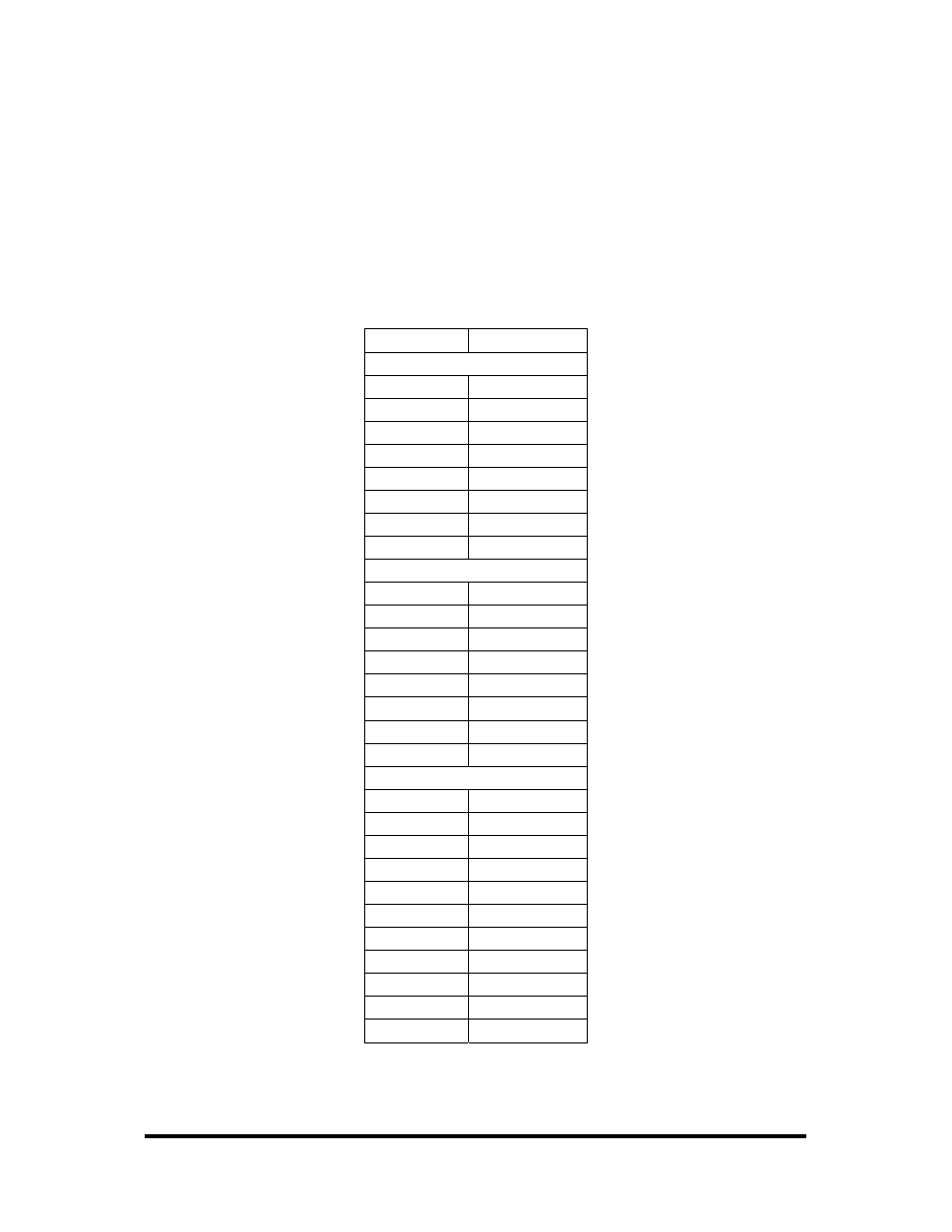
The following table shows the correlation between the port addresses and the 50-pin
connections.
Description
Pin #
Port A
A0 47
A1 45
A2 43
A3 41
A4 39
A5 37
A6 35
A7 33
Port B
B0 31
B1 29
B2 27
B3 25
B4 23
B5 21
B6 19
B7 17
Port C
C0L 15
C1L 13
C2L 11
C3L 9
C4U 7
C5U 5
C6U 3
C7U 1
GND
All Even pins
+5V
49
- PCW-5181 (120 pages)
- PCM-4373 (2 pages)
- EPIC-5536 (2 pages)
- EPIC-CV07 (2 pages)
- EPIC-QM57 (2 pages)
- EPIC-QM77 (2 pages)
- VSX-6118-V2 (1 page)
- VSX-6116-V2 (1 page)
- VSX-6115-V2 (1 page)
- VSX-6114-V2 (1 page)
- VDX-6318RD (1 page)
- VDX-6316RD (1 page)
- VDX-6315RD (1 page)
- VDX-6314RD (1 page)
- PCM-5895 Rev. A (2 pages)
- PCM-8120 (2 pages)
- PCM-9562 (3 pages)
- VSX-6127-V2 (1 page)
- PCM-9375 (3 pages)
- GENE-5315W1 Rev. B (2 pages)
- GENE-5315 Rev. A (2 pages)
- VDX-6327RD (1 page)
- VDX-6328RD (1 page)
- VDX-6329RD (1 page)
- VDX-6326RD (1 page)
- PCM-9343 (3 pages)
- GENE-9655 (2 pages)
- PCM-9362 (2 pages)
- GENE-LN05W2 Rev. B (2 pages)
- PCM-9363 (3 pages)
- GENE-TC05W2 (2 pages)
- GENE-CV05W2 (2 pages)
- SBC-210 (1 page)
- GENE-QM57 (2 pages)
- GENE-QM67 (2 pages)
- GENE-QM77 Rev B (2 pages)
- GENE-QM77 Rev A (2 pages)
- GENE-QM87 (1 page)
- EL630-NR (2 pages)
- EL620-C (2 pages)
- SB601-C (2 pages)
- SB600-C (2 pages)
- SB630-CRM (2 pages)
- CL630-CRM (2 pages)
- DL631-C226 (2 pages)