Dip switch configuration, Dip switch "b, Dip switch "a – Controlled Products Systems Group RAM100 User Manual
Page 12
9
www.ramsetinc.com
RAMSET
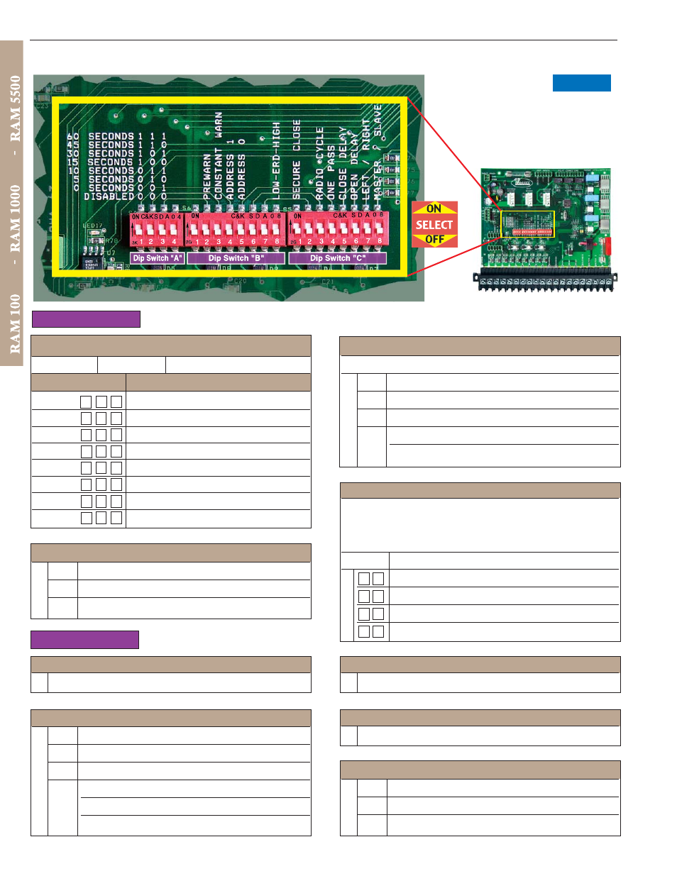
DIP SWITCH "B"
DIP SWITCH CONFIGURATION
DIP SWITCH "A"
Dip Switch "A" 1, 2 & 3; AUTOMATIC TIMER TO CLOSE GATE
‘0’ is “OFF” ‘1’ is “ON”
Switch
1 2 3
Gate Open Duration:
1 1 1
60 seconds
1 1 0
45 seconds
1 0 1
30 seconds
1 0 0
15 seconds
0 1 1
10 seconds
0 1 0
05 seconds
0 0 1
00 seconds
0 0 0
disabled - command required to close
Dip Switch "A" 4; 1/2 HP E.R.D.
Sw. Function:
OFF No
Function.
ON
Setting for stronger E.R.D.
Dip Switch "B" 1; Not in use at this time.
Leave in the ‘
Off
’ position.
Dip Switch "B" 2; “PREWARN”
Sw. Pre Warning Relay:
OFF Normal
Operation
ON
Adds a 3-second delay before the gate moves in
any direction. During This 3 second delay the
PREWARN Relay maintains a closed contact.
Dip Switch "B" 3; “CONSTANT WARN”
(Constant warning when gate is in motion).
Sw. Function:
OFF No
effect.
ON
Triggers the prewarn relay to maintain a closed
contact while gate is in motion.
Dip Switch "B" 6; Not in use at this time.
Leave in the ‘
Off
’ position.
Dip Switch "B" 7; Not in use at this time.
Leave in the ‘
Off
’ position.
Dip Switch "B" 8; E.R.D.
Sw. Function:
OFF “Low” E.R.D. for 1/2 HP motors
ON
“High” E.R.D. for 3/4 HP motors
Dip Switch "B" 4 & 5; “ADDRESS 1 & ADDRESS 0”
Up to four separate entrance addresses are available for
installations with multiple entrance or exit locations. Master and
slave gates that work together should be set to the same
address. (side gates use the address setup)
Sw. 4 5 Function:
0 0
Default - Entrance 1
0 1
Entrance 2
1 0
Entrance 3
1 1
Entrance 4
"Intelligate" Control Board
Figure 11