Wiring, Earth ground rod installation (optional), Warning caution warning warning – Controlled Products Systems Group LA400-S User Manual
Page 13
13
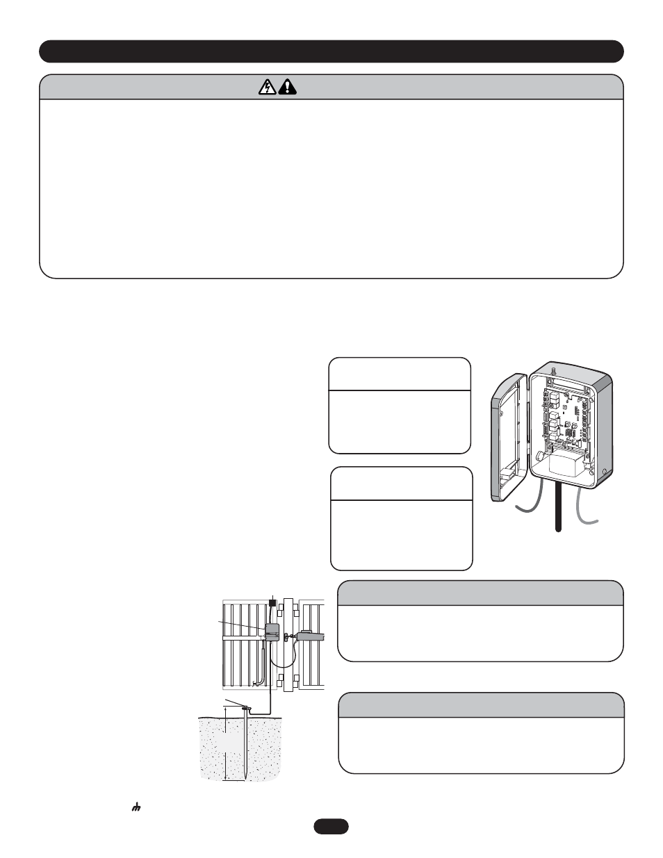
120VAC POWER WIRE
(STRANDED COPPER WIRE)
NOTE: Calculated using NEC guidelines. Local codes and conditions must be reviewed for suitability of wire installation.
To reduce the risk of SEVERE INJURY or DEATH:
• ANY maintenance to the operator or in the area near the
operator MUST not be performed until disconnecting the
electrical power and locking-out the power via the operator
power switch. Upon completion of maintenance the area MUST
be cleared and secured, at that time the unit may be returned
to service.
• Disconnect power at the fuse box BEFORE proceeding.
Operator MUST be properly grounded and connected in
accordance with local electrical codes. NOTE: The operator
should be on a separate fused line of adequate capacity.
• ALL electrical connections MUST be made by a qualified
individual.
• DO NOT install ANY wiring or attempt to run the operator
without consulting the wiring diagram. We recommend that
you install an optional reversing edge BEFORE proceeding with
the control station installation.
• ALL power wiring should be on a dedicated circuit and well
protected. The location of the power disconnect should be
visible and clearly labeled.
• ALL power and control wiring MUST be run in separate
conduit.
• BEFORE installing power wiring or control stations be sure to
follow ALL specifications and warnings described below.
Failure to do so may result in SEVERE INJURY to persons
and/or damage to operator.
Wire Gauge
Length
16
100' (30 m)
10
1000' (305 m)
WARNING
CAUTION
WARNING
WARNING
EARTH GROUND ROD INSTALLATION (OPTIONAL)
When installing the optional earth ground rod, disconnect and
remove the green/yellow ground wire connected to the screw
terminal of the printed circuit
board. For proper operation,
the earth ground rod should
not be connected to the
ground of your power wiring.
Ensure the power wiring
ground connection remains
securely connected to the
green screw on the outlet
plate.
The earth ground rod must be
located within 3 feet (0.9 m) of
the operator. Use the proper
type earth ground rod for your
area.
Attach earth ground rod wire to the screw terminal of the printed
circuit board marked
.
To AVOID damaging gas, power or other underground utility
lines, contact underground utility locating companies BEFORE
digging more than 18" (46 cm) deep.
Earth Ground
Installation
(Optional)
12 gauge
wire
8 ft.
(2.4 m)
Control Box
WARNING
CAUTION
WARNING
WARNING
All power wiring should be on a dedicated circuit and well protected.
24VAC TRANSFORMER
(STRANDED COPPER WIRE)
Wire Gauge
Length
16
100' (30 m)
14
500' (152 m)
12
1000' (305 m)
Control
Wiring
Power
Wiring
Motor
Wiring
The transformer is tie-wrapped at the factory for shipping. The
transformer can be plugged into a receptacle external to the
control box. You can run low voltage wire between the
transformer and control box. This will create more space in the
control box for accessories.
Alternatively, you can connect 120Vac directly to the box, and
plug the transformer to the receptacle inside the control box.
CONNECT ARM TO CONTROL BOX
Connect the wires from the operator to connector P17 for the
Gate 1 operator as shown in the wiring diagram on page 26.
Connect the proper color coded wire to the terminal pin as
indicated. Use supplied strain relief.
If connecting a second arm, follow the same instructions on
connector P16.
W I R I N G
To AVOID damaging plug-in transformer, it MUST be enclosed
in a suitable weatherproof enclosure and provided with proper
weatherproof fixtures.
WARNING
CAUTION
WARNING
WARNING