Figure 4 – Controlled Products Systems Group LA400-S User Manual
Page 11
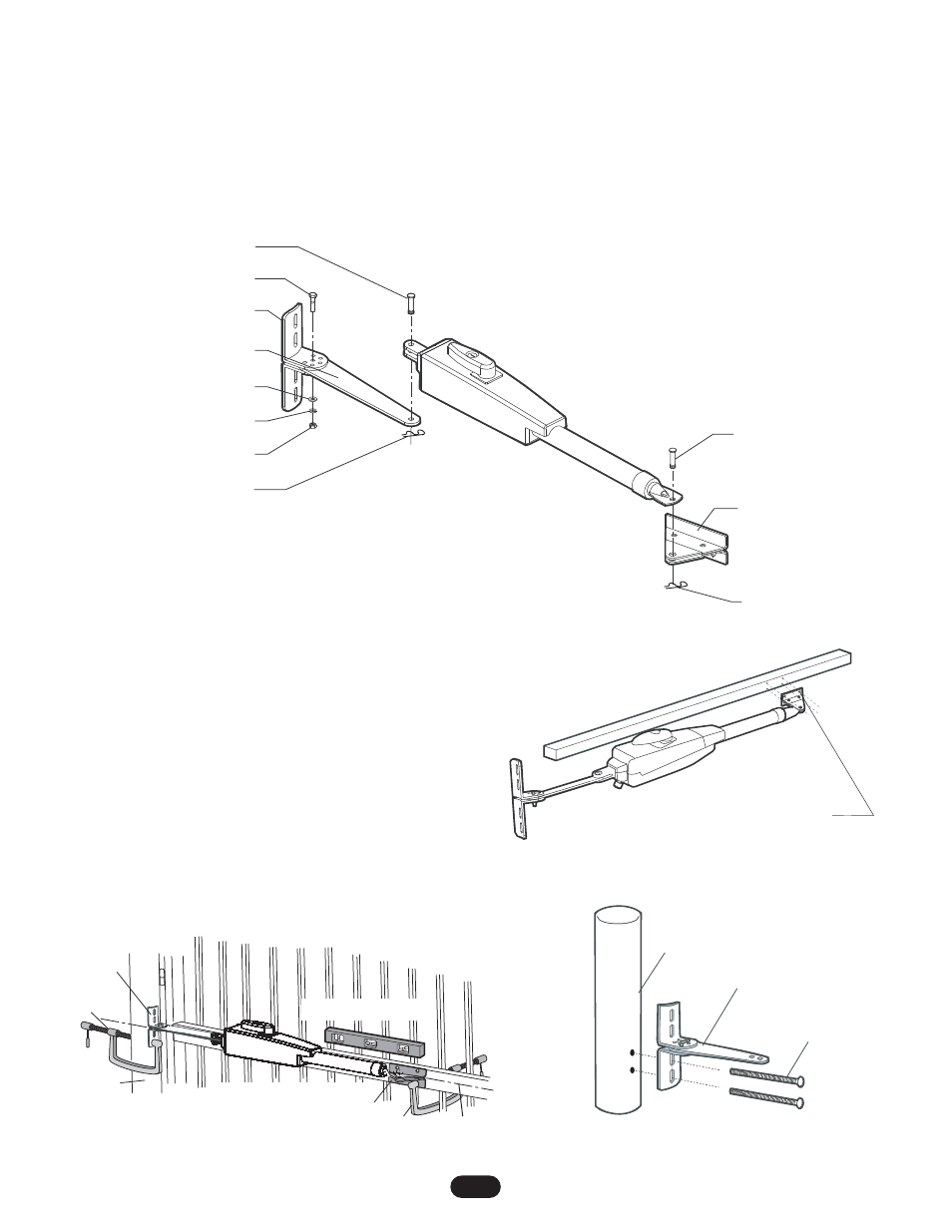
Hex Bolt
Post Bracket
Push-to-Open Bracket
Flat Washer
Lock Washer
Nut
Pin
Pin
Hairpin Clip
Hairpin Clip
Gate Bracket
Figure 4
11
7. Remove pins and detach operator.
8. Mark holes for post bracket assembly and gate bracket. Be
sure to mark holes in the vertical center of post bracket slots.
NOTE: All four mounting holes must be used.
9. Remove brackets from gate post and cross member.
10. Drill 13/32" holes in marked locations for gate posts and
11/32" for gate bracket.
11. Secure gate posts bracket assembly to gate post using 3/8"
bolts, lock washer, flat washer and nuts. Secure gate bracket
to cross member using 5/16" bolts, lock washer, flat washer
and nuts (Figures 6 & 7).
12. Reattach operator to gate using pins and hairpin clips.
NOTE: After final limit adjustments (page 21) the gate can be
closed slightly further by increasing the distance between center
of gate hinge and the gate bracket by 1" (25.4 mm). Do not move
the post bracket assembly.
Gate In Open Position
Mark cross member through middle of
gate bracket slots and drill 11/32" holes
LEV
EL Horizontal Cross Member
Figure 6
Post Bracket
Assembly
Mark fence post through
middle of bracket slots
and drill 13/32" holes
3/8"-16 x 6"
Carriage Bolt
Figure 7
Fence Post
Post Bracket
Assembly
Gate In CLOSED Position
Gate Bracket
C Clamp
C Clamp
Operator MUST be level
Horizontal Center of
Gate Cross Member
Figure 5
4. Attach operator to gate post bracket by inserting
push-to-open bracket into slot on the motor side of operator.
Secure with pin (Figure 4).
5. Fasten gate bracket to the actuator side of the operator using
pin. Swing operator to the desired closed position (Figure 4).
6. Position gate to full closed position. Adjust operator until it is
level and position bracket against the cross member. Secure
using C clamp (Figure 5).