Controlled Products Systems Group LA400-S User Manual
Page 10
10
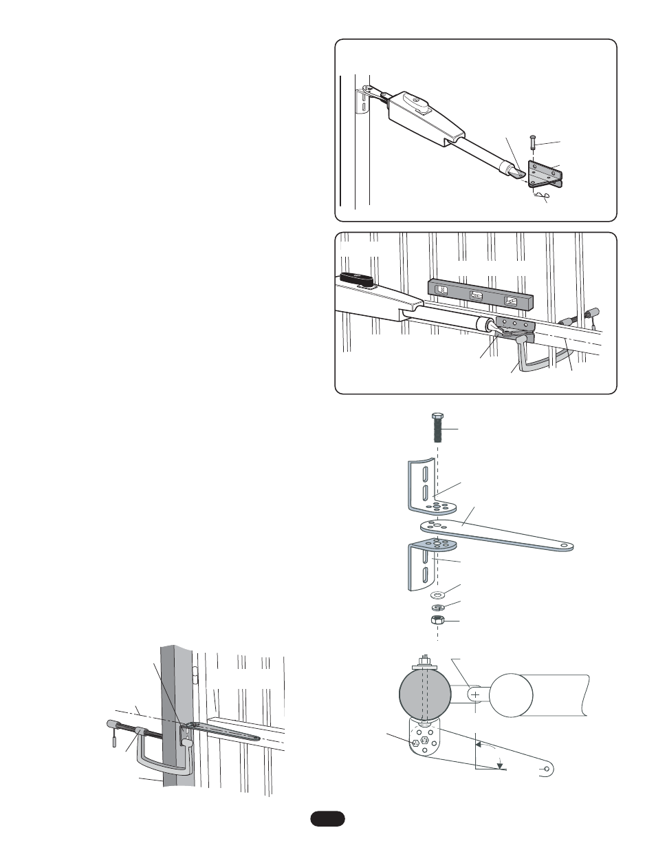
PUSH-TO-OPEN BRACKET MOUNTING
INSTRUCTIONS (FOR USE WITH ACCESSORY KIT
50-19503)
1. Place push-to-open bracket between the two post brackets.
Insert 3/8" hex bolt through middle hole and secure with lock
washer, flat washer and nut (Figure 1).
2. Determine the vertical position of the gate post bracket
assembly on the gate post by aligning the gate post bracket
with one of the cross members of the gate (Figure 2). For
optimal performance, align the gate post bracket to a cross
member that is as close to the vertical center of the gate post
as possible. Level gate post bracket, mark holes and
temporarily secure to gate post using C clamp (Figure 2).
3. Rotate the push-to-open bracket to obtain desired dimensions
(Figure 3).
3/8" Hex Bolt
3/8" Nut
Push-to-Open Bracket
Post Bracket
Post Bracket
3/8" Flat Washer
3/8" Lock Washer
Figure 1
Center of Gate Hinge
Special Post Pivot Bracket for
Push-to-Open Installation
90˚
5/16" Hex Bolt
7-3/4"
(19.7 cm)
7-3/4"
(19.7 cm)
Figure 3
5. Fasten gate bracket to the actuator side of the operator using
pin. Swing operator to the desired open position (Figure 5).
6. Open gate to full open position (Do not exceed 100°). Adjust
operator until it is level and position bracket against the cross
member. Secure using C clamp (Figure 6).
7. Remove pins and detach operator.
8. Mark holes for post bracket assembly and gate bracket. Be
sure to mark holes in the vertical center of post bracket slots.
NOTE: All four gate bracket mounting holes must be used.
9. Remove brackets from gate post and cross member.
10. Drill 13/32" holes in marked locations for gate posts and
11/32" for gate bracket.
11. Secure gate posts bracket assembly to gate post using 3/8"
bolts, lock washer, flat washer and nuts. Secure gate bracket
to cross member using 5/16" bolts, lock washer, flat washer
and nuts.
12. Reattach operator to gate using pins and hairpin clips.
NOTE: After final limit adjustments (page 21) the gate can be
opened slightly further by increasing the distance between center
of gate hinge and the gate bracket by 1" (25.4 mm). Do not move
the post bracket assembly.
Gate In OPEN Position
Gate Bracket
C Clamp
Operator MUST be level
Horizontal Center of
Gate Cross Member
Figure 6
Pin
Gate Bracket
Actuator Side
Hairpin Clip
Figure 5
Post Bracket
Assembly
C Clamp
Fence
Post
Gate In
CLOSED Position
Horizontal
Center of Gate
Cross Member
Figure 2