Control box mounting, Control box mounting with u-bolts(optional kit), Control box mounting with u-bolts (optional kit) – Controlled Products Systems Group LA400-S User Manual
Page 12
12
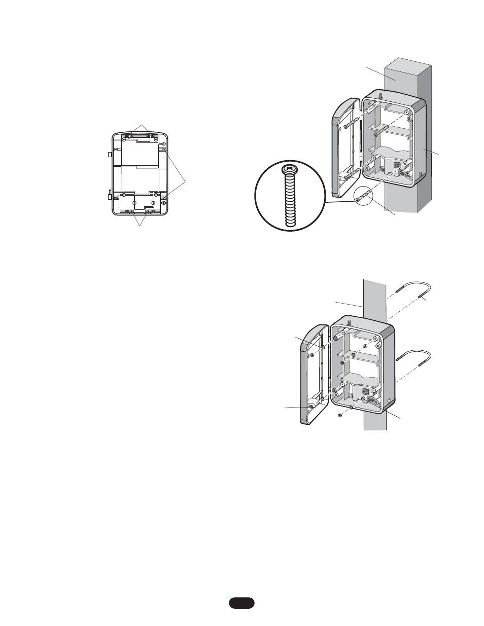
Figure 1
4" (10 cm) Screw Spacing (4)
6" (15 cm) Screw
Spacing (4)
2-1/2" (6.3 cm) Screw Spacing (4)
CONTROL BOX MOUNTING WITH U-BOLTS
(OPTIONAL KIT)
1. Remove PCB and batteries.
2. Determine the spacing required for mounting and select the
proper holes to be used for mounting (Figure 1).
3. Knockout plastic from holes using screw driver.
4. Center the box up against the mounting post. Insert the U-bolts
through the mounting holes in back (Figure 3).
5. Once the U-Bolts are in place, insert the rubber washer,
followed by the metal washer and 1/4"-20 Nut (Figure 3).
6. Tighten the assembly down snug after positioning it as desired.
Optional kits available are:
50-19509 6" (15 cm) Post Mounting
50-19511 4" (10 cm) Post Mounting
50-19512 2-1/2" (6.3 cm) Post Mounting
Mounting screw
4 places
Figure 2
Mounting Post
E-Box
Mounting Post
1/4" Washer (4)
1/4"-20
Hex Nut (4)
1/4" Washer (4)
Figure 3
U-Bolt (2)
CONTROL BOX MOUNTING
1. Remove PCB and batteries.
2. Determine the spacing required for mounting and select the
proper holes to be used for mounting (Figure 1).
3. Knockout plastic from holes using screw driver.
4. Place box up against the mounting surface. Insert the screws
through the mounting holes in back and secure in place
(Figure 2).