Operator and arm layout – Controlled Products Systems Group AOMSW350DC User Manual
Page 9
X
X
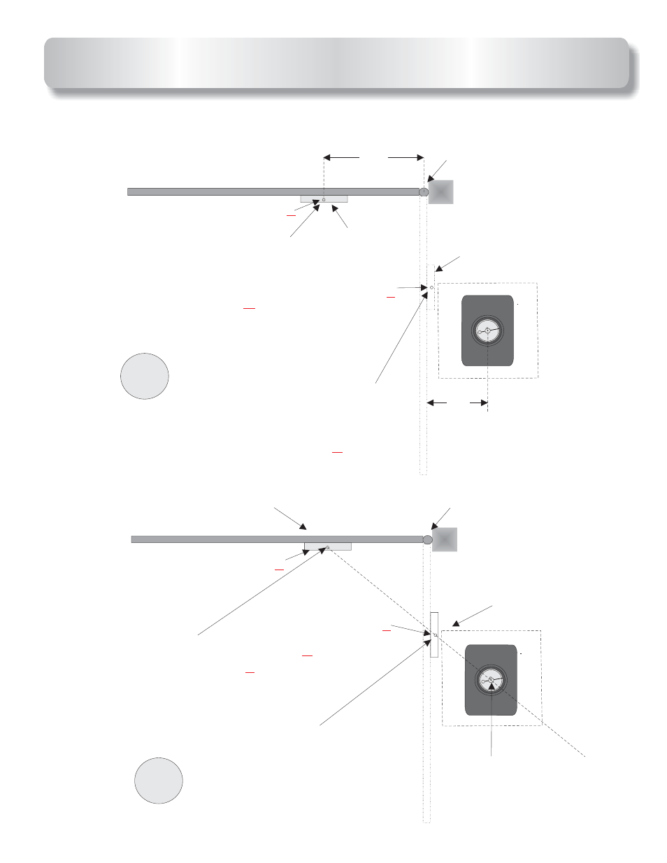
Hinge point
Hinge point
Bracket
Bracket
Bracket
Bracket
Mark ground under
gate bracket with
gate closed. This will
be point
Y
Mark ground under
gate bracket with
gate open. This will
be point
Z
14”
“A”
Center shaft of
Operator
1
2
X
X
Point
Y
Point
Y
Point
Z
Point
Z
Out
In
Out
In
OPERATOR AND ARM LAYOUT
Draw a line from point
past the point
as shown.
This should be laid on the
ground. The operators
center shaft goes on this
line.
Y
Z
8
See also other documents in the category Controlled Products Systems Group Safety:
- GNC-1 (1 page)
- -108712 (33 pages)
- 1044372 (28 pages)
- 1042071277 (28 pages)
- 104207177 (28 pages)
- 104301 (30 pages)
- 10441811 (29 pages)
- 1044182 (28 pages)
- 1044682 (28 pages)
- 104471 (28 pages)
- 104572 (24 pages)
- 104572 (27 pages)
- 10468583 (36 pages)
- 1049062 (17 pages)
- 106753 (28 pages)
- 108758 (40 pages)
- 109773 (19 pages)
- 10978021 (6 pages)
- 109902 (27 pages)
- 1150-080 (30 pages)
- 1600 (17 pages)
- 1650ETL (23 pages)
- 1650ETL-1K (32 pages)
- 1601-081 (36 pages)
- 1602-091 (42 pages)
- 1602-091 (42 pages)
- 1603-166 (38 pages)
- 1603-166 (42 pages)
- 1603-166 (40 pages)
- 444 XS ST (98 pages)
- 222X383 (84 pages)
- 3020HX (24 pages)
- 3600ETL-1K (36 pages)
- 4500SW (32 pages)
- 6004-080 (34 pages)
- 6002-080 (32 pages)
- 6003-080 (22 pages)
- 6100-083 (46 pages)
- 6100-083 (56 pages)
- 6100-083 (2 pages)
- 6300-087 (59 pages)
- 6300-087 (52 pages)
- 6400-080 (28 pages)
- 6500-087 (48 pages)
- 6500-087 (46 pages)