Arm layout & operator placement continued – Controlled Products Systems Group AOMSW350DC User Manual
Page 10
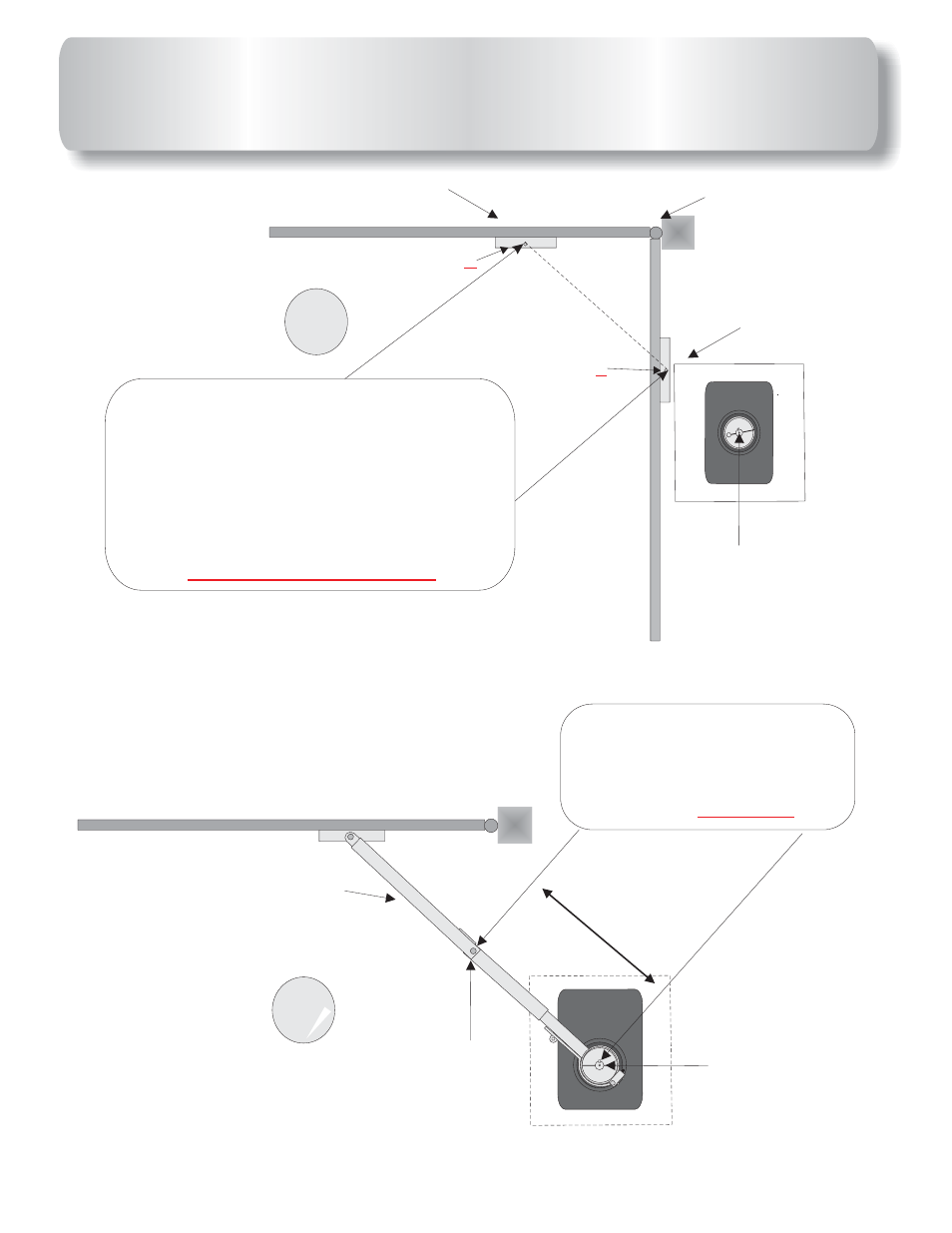
ARM LAYOUT & OPERATOR
PLACEMENT CONTINUED
Hinge point
Bracket
Bracket
Center shaft of
Operator
3
Measure distance from the
Y
Z.
point
And point
Say distance is 60”,
divide this number by 2,which =30”.
This is the length of primary arm in
next drawing.
PLEASE BE EXACT!!!
4
+
T
his ARM section is half the
distance between point
and point
as shown above.
Y
Z
IT MUST BE EXACT!!!
This pipe does not need to
be measured after primary
arm is installed this pipe
makes up the balance of
arm.
PRIMAR
Y ARM SECTION
CENTER OF
BOLT AT FIRST
HINGE POINT
CENTER OF
SHAFT ON
OPERATOR
X
X
Point
Y
Point
Z
+
9
See also other documents in the category Controlled Products Systems Group Safety:
- GNC-1 (1 page)
- -108712 (33 pages)
- 1044372 (28 pages)
- 1042071277 (28 pages)
- 104207177 (28 pages)
- 104301 (30 pages)
- 10441811 (29 pages)
- 1044182 (28 pages)
- 1044682 (28 pages)
- 104471 (28 pages)
- 104572 (24 pages)
- 104572 (27 pages)
- 10468583 (36 pages)
- 1049062 (17 pages)
- 106753 (28 pages)
- 108758 (40 pages)
- 109773 (19 pages)
- 10978021 (6 pages)
- 109902 (27 pages)
- 1150-080 (30 pages)
- 1600 (17 pages)
- 1650ETL (23 pages)
- 1650ETL-1K (32 pages)
- 1601-081 (36 pages)
- 1602-091 (42 pages)
- 1602-091 (42 pages)
- 1603-166 (38 pages)
- 1603-166 (42 pages)
- 1603-166 (40 pages)
- 444 XS ST (98 pages)
- 222X383 (84 pages)
- 3020HX (24 pages)
- 3600ETL-1K (36 pages)
- 4500SW (32 pages)
- 6004-080 (34 pages)
- 6002-080 (32 pages)
- 6003-080 (22 pages)
- 6100-083 (46 pages)
- 6100-083 (56 pages)
- 6100-083 (2 pages)
- 6300-087 (59 pages)
- 6300-087 (52 pages)
- 6400-080 (28 pages)
- 6500-087 (48 pages)
- 6500-087 (46 pages)