Pad and operator location, Important installation instructions, 18” m in. electrical stub ups y – Controlled Products Systems Group 3020HX User Manual
Page 6
6
IMpORTanT InSTallaTIOn InSTRuCTIOnS
DR 3020/DR 3020HX/DRT 3520
GaTe OpeRaTIOn
The gate must roll freely with no binding of the wheel, guides, and/or gate hardware before any operator is
connected to the gate.
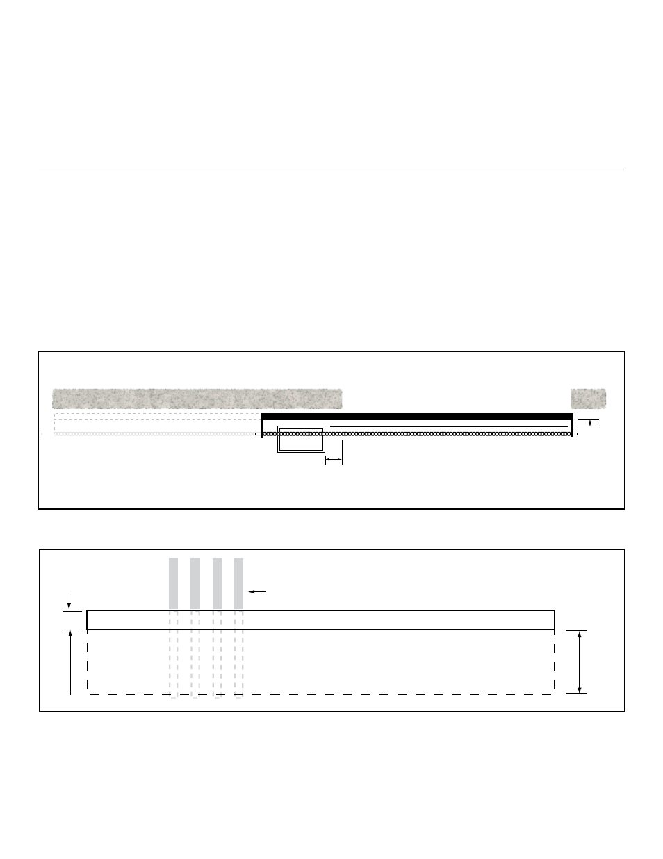
paD anD OpeRaTOR lOCaTIOn
Position the pad as indicated in Figure #1. Failure to do so may cause erratic operation resulting in reduced
operator life.
Important: If the gate is not at least twenty-eight inches longer than the opening, an extension should be added
to the rear portion of the gate fir the mounting of the rear chain bolt bracket. See Fig #2 The
extension must be rigid and long enough to allow the gate to fully close without the rear chain bolt
bracket hitting the operator.
Note:
If there is already concrete where the operator is to be mounted, a pad is not necessary, if the existing
concrete is level.
Gate Closed Position
4”
1”
Concrete Pad
DR 3020 / DR 3020HX / DRT3520
Gate Open Position
Figure 1 (Front Mount)
Concrete Pad Construction and Layout
18”
M
in.
Electrical Stub Ups
Y
Figure 2 (Side View)
Y dimension in Figure 2 must be high enough so that water will not stand under the operator in a worst case
scenario.
Soil conditions may vary but in sandy or loose soil the pad should be at least 18”-24” inches deep.