Front panel indicators and buttons, Ront, Anel – CTI Products NCB/IM with Internal PSTN Modem User Manual
Page 12: Figure 3 ncb/im module front panel
CTI Products, Inc.
NCB/IM User Guide
1. Introduction
6
F
RONT
P
ANEL
1 2 3 4 5 6 7 8
ON
OPTION A
DC IN
ERR
ACT
PWR
NETWORK
OUT
IN
RSVC
CSVC
AUDIO
LINE
CD OH
RESET
CMD
NCB
NETWORK COMBINER
NETWORK
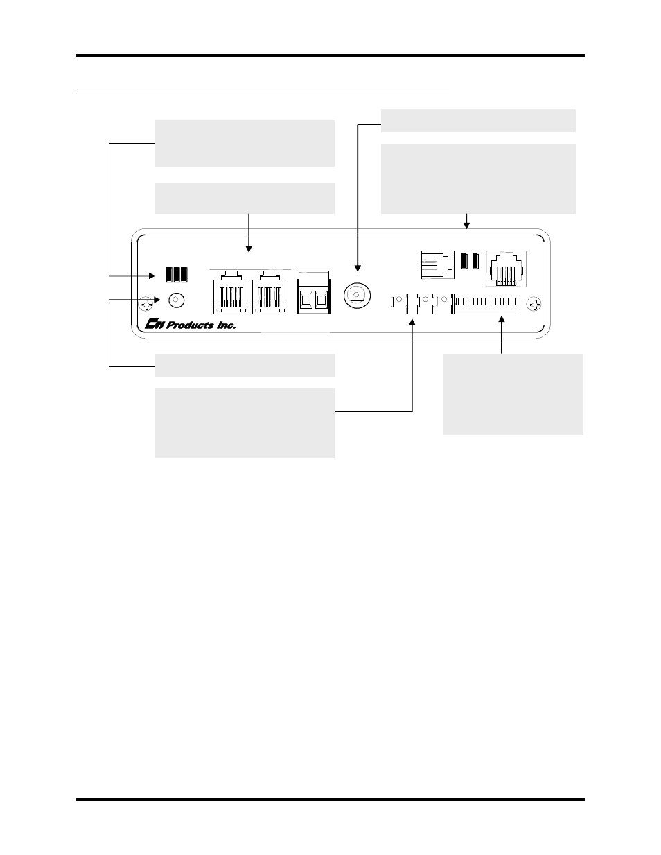
Figure 3 NCB/IM Module Front Panel
Front Panel Indicators and Buttons
PWR LED (Green) - Indicates condition of DC input power or a “Wink” command.
Always On: Correct DC input power is present.
Flashing Continuously: DC input to module is below minimum required voltage.
Flashes for 2 Seconds: A “Wink” network management command has been sent to the Control
Neuron Processor.
ERR LED (Red) – Indicates a possible error condition.
Always On: A diagnostic error has been detected. Press the “RESET” button. If the “ERR” LED now
stays off, the EEPROM contained invalid data and has been reinitialized. Any non-volatile
information must be re-entered by using the NCB/Plug configuration plug-in or the DOS NCBCON
program.
If the LED stays on solid, a hardware problem is indicated. Contact technical support for
assistance.
Slow Flash: (once per second) L
ON
W
ORKS
configuration information is insufficient. Using a
Network Management Tool, re-commission the internal router nodes (and optionally, the Control
Neuron Processor node).
ACT LED (Yellow) - Indicates a packet has been passed by the NCB router.
OH LED (Green) - Indicates the modem is OffHook.
CD LED (Yellow) - Indicates the modem has detected carrier and completed the training sequence with the
distant modem.
PWR LED Indicates correct input power
ERR LED
Indicates an error condition
ACT LED
Indicates LonWorks packet
activity in router
LonWorks NETWORK Connections
RJ45 and Screw Terminal
DC IN Connector for input power
AUDIO Connector Simultaneous Voice/Data
CD LED
Carrier Detected and
training sequence
completed
OH LED
Off Hook condition
LINE Connector
Telco connection
RESET Button
CMD Button Temporarily enables Auto-
Answer mode (see below)
CSVC Button Initiates Service Request
from Control Neuron
RSVC Button Initiates Service Request
from Router
OPTION A Switches
Selects Internal Modem
and LonWorks Addressing
parameters.
(See Setup and
Operation for more detail)