CTI Products NCB/IM with Internal PSTN Modem User Manual
Page 17
CTI Products, Inc.
NCB/IM User Guide
2. Setup and Operation
11
2) OPTION A Switch 7 is used to set the transmit level from the modem and should be normally
left in the UP position. If two NCB units are to be connected “back-to-back” in Leased-Line
mode with only a short cable between the “LINE” connector on each unit (in lab test
situations, for instance), Switch 7 must be set to the DOWN position in order for the two
modems to connect properly.
3) OPTION A Switch 8 should be set to match the type of leased telephone line being connected
: 2-wire or 4-wire.
Setting the L
ON
W
ORKS
Addressing Parameters (Switches 5 and 6)
Switches 5 and 6 provide a simple (but very limited) method of setting the L
ON
W
ORKS
domain/subnet/node
address of the internal Control Neuron Processor. This method is useful for systems with two NCB modules,
but does not provide enough flexibility for larger systems. (Standard Network Management Tools are a much
better choice.) For more information on setting this address, see “S
for a tutorial on network management tools.
If OPTION A Switch 5 is UP, Switch 6 determines a static subnet/node address for the Control Neuron
Processor: Switch 6 DOWN fixes the Control Neuron Processor subnet/node address at 255/1 in the
zero-length domain, while Switch 6 UP fixes the subnet/node address at 255/2 in the zero-length
domain. This setting allows for a quick evaluation of the NCB modules, requiring minimal user setup.
If OPTION A Switch 5 is DOWN, dynamic determination of the domain/subnet/node number by a
Network Management Tool is allowed.
S
TEP
3.
E
LECTRICAL
C
ONNECTIONS
L
ON
W
ORKS
Network Connection
The local L
ON
W
ORKS
network must be attached to the NCB module via the “NETWORK” connector following
standard Echelon guidelines as to cable type, cable length, and termination appropriate for the selected
transceiver.
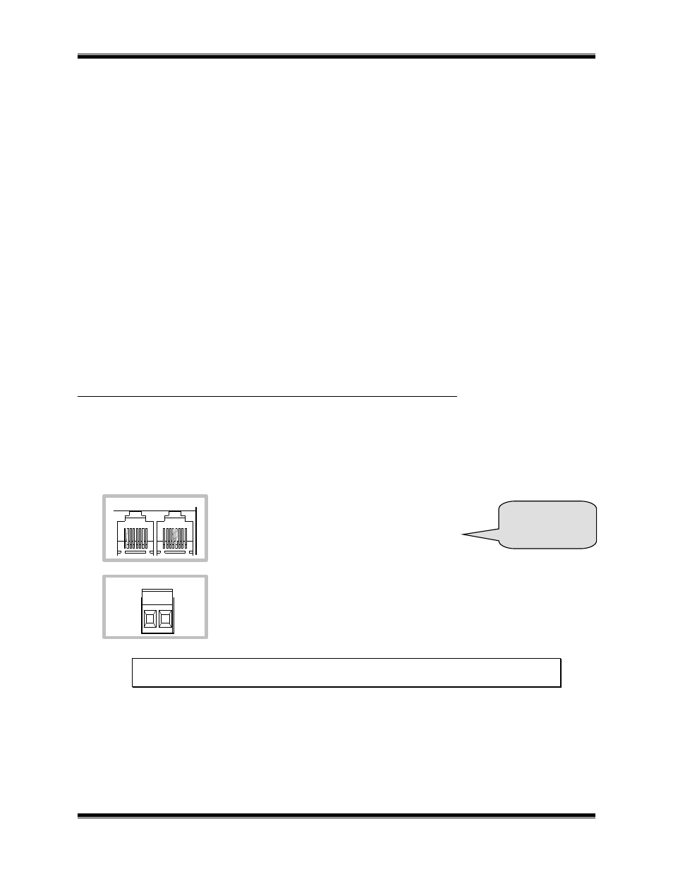
The dual RJ45 “NETWORK” connector allows a
daisy-chained network connection method, as the
network pins of the two RJ45 connector are directly
paralleled. Note that other pins on the RJ45 are
connected to circuit ground and DC power.
The 2 pin removable terminal strip is wired in parallel with the network connections
on the dual RJ45 connector.
NOTE: If your NCB module was purchased without a L
ON
W
ORKS
transceiver (SMX-ready),
refer to Technical Note TN025 to install your SMX transceiver.
NETWORK
OUT
IN
NETWORK
See Appendix C
for Connector
Details