Line port, Data flow, Figure 2 ncb network combiner block diagram – CTI Products NCB/IM with Internal PSTN Modem User Manual
Page 10
CTI Products, Inc.
NCB/IM User Guide
1. Introduction
4
NCB units are available with an option for L
ON
W
ORKS
network transceiver type. The ordering code on the rear
of the NCB lists the installed options. This ordering code is of the form: NCB/IM-Txxx-xx, where ‘T’
indicates the transceiver type.
The following L
ON
W
ORKS
network transceiver options are available:
A = FTT-10A
K = SMX RS485
B = TPT/XF-78
M = SMX PL22
C = TPT/XF-1250
X = None (SMX ready)
Line Port
The internal modem in the NCB/IM module uses proven V.32 terbo modulation, transferring data at 19,200 bits
per second. Dial-up as well as 2-wire and 4-wire leased lines are supported.
The internal modem is unique in its ability to transfer voice simultaneous to data using only a single voice-grade
circuit between two NCB modules. This bidirectional voice channel exists between each NCB module pair and
is accessible via the “AUDIO” connector on the NCB module. This live voice feature can be used in any
application that requires live data as well as voice communication between personnel or equipment at separate
sites.
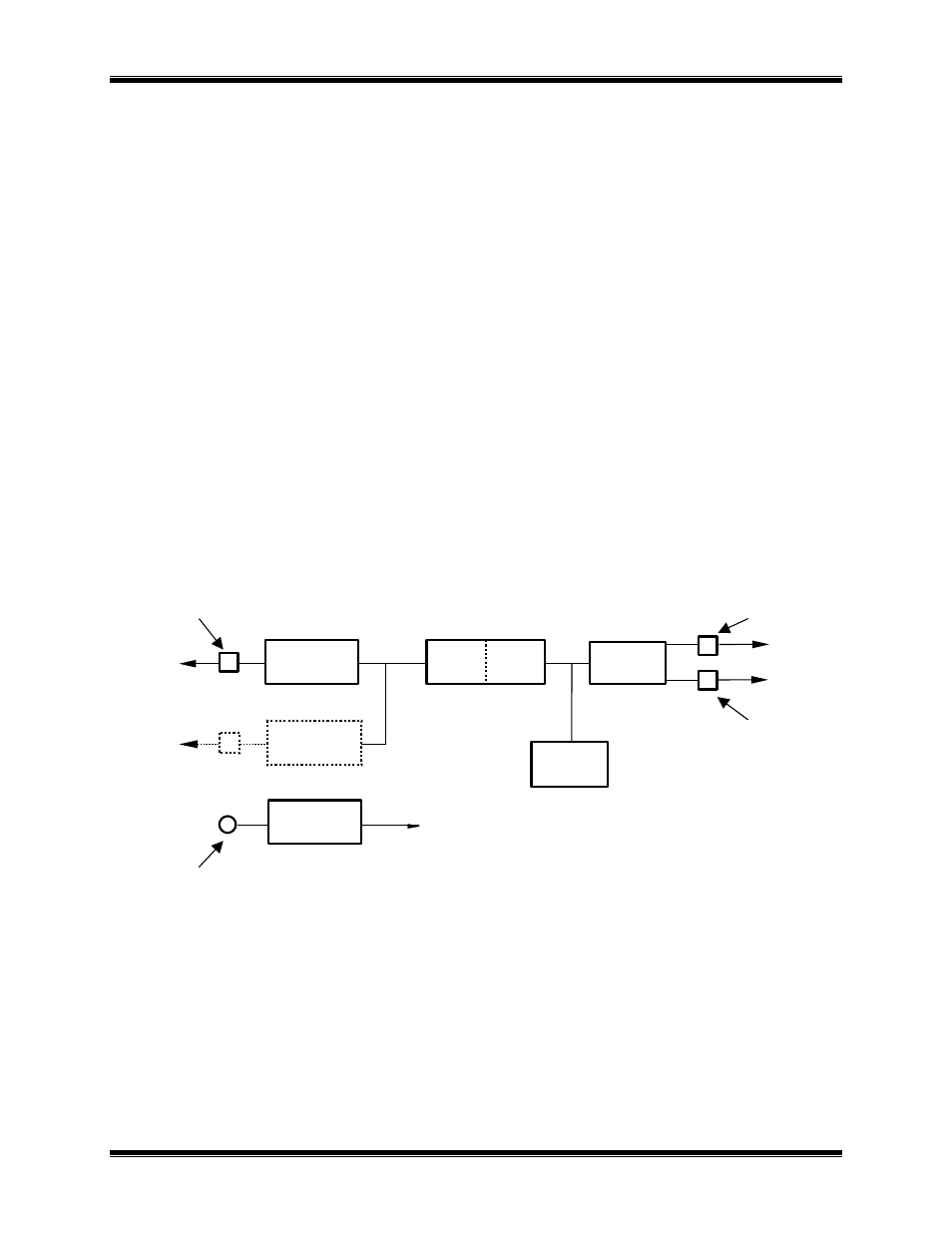
Data Flow
There are three sources of message packets within the NCB module. The first source is the L
ON
W
ORKS
NETWORK connector on the front of the unit. The second is the Telco “LINE” connector on the front of the
unit. The third source is the Control Neuron
Processor. Message packets originating from any of these
sources are sent to the other two. This message packet flow is shown in the block diagram of Figure 2.
LONWORKS
NETWORK
Side
A
ROUTER
LONWORKS
TRANSCEIVER
“DC IN”
Connector
“NETWORK”
Connector
“AUDIO”
Connector
“LINE”
Connector
To TELCO
CIRCUIT
Side
B
SMX
TRANSCEIVER
POWER
SUPPLY
CONTROL
NEURON
PROCESSOR
INTERNAL
MODEM
To
HANDSET
Figure 2 NCB Network Combiner Block Diagram
The “NETWORK” connector attaches to the local L
ON
W
ORKS
network using a compatible transceiver
internal to the NCB module and is associated with Side B of the internal router.
The “LINE” connector attaches to the telephone circuit as the link to the NCB unit at the other network site
and is associated with Side A of the internal router.
The Control Neuron
Processor allows network management messages to be sent to the NCB module for
connection control and status monitoring and is associated with Side A of the internal router.