Front panel, Front panel indicators – additional information, Ront – CTI Products NCB/FL with Fiber Interface User Manual
Page 8: Anel, Figure 3 ncb-etherlon and ncb-fiberlon front panel
CTI Products, Inc.
NCB-EL/FL User Guide
2. Installation
5
F
RONT
P
ANEL
1
2
3
4
5
9
8
7
6
ERR
ACT
PWR
RESET
WINK
ETH RX
ETH TX
CSVC
RSVC
NETWORK
OUT
IN
ASYNC
NETWORK
NCB
NETWORK COMBINER
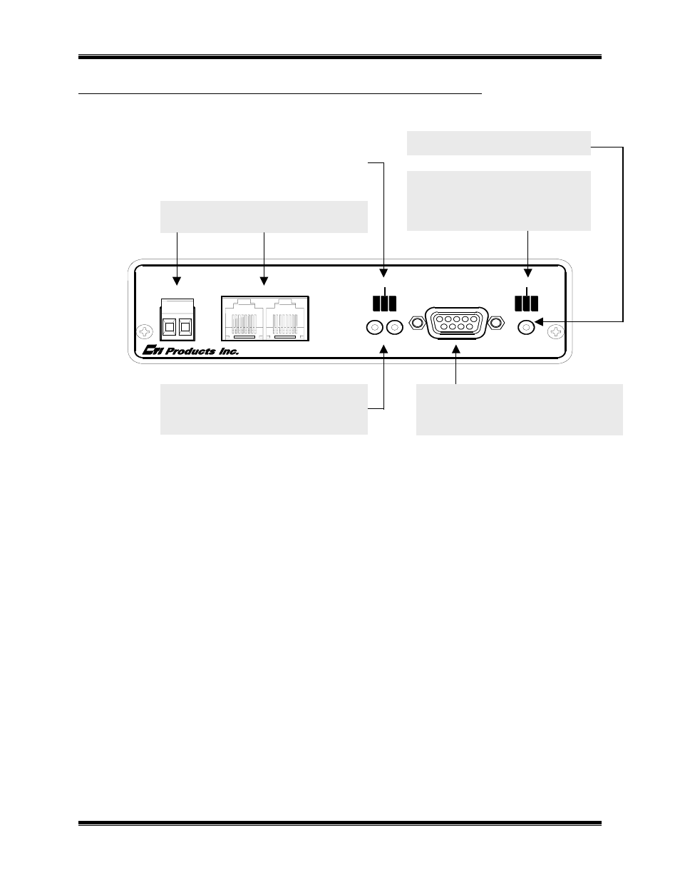
Figure 3 NCB-Etherlon and NCB-Fiberlon Front Panel
Front Panel Indicators – Additional Information
ETH RX LED (Yellow) – Indicates when a packet has been detected on the Ethernet port. NOTE: Flashing of
this LED does NOT necessarily mean that a packet addressed to this Etherlon module has been received, just
that a packet has been detected on the Ethernet network.
ERR LED (Red) – Indicates a possible error condition.
• Always On: A diagnostic error has been detected. Press the “RESET” button. If the “ERR” LED now
stays off, the EEPROM contained invalid data and has been reinitialized. Any non-volatile
information must be re-entered by using the EtherPlug program.
If the LED stays on solid, a hardware
problem is indicated. Contact technical support for assistance.
• Slow Flash: (once per second) L
ON
W
ORKS
configuration information is insufficient. Using a
network management tool, re-commission the internal router nodes (and optionally, the Control
Neuron Processor node).
• Quick Flash: (twice per second) IP address configuration is insufficient. Using EtherPlug, configure
the IP addressing parameters.
LonWorks NETWORK Connections
Screw Terminal and RJ-45
ASYNC Connector
Used with EtherPlug to access IP
address parameters
RESET Button
CSVC Button Initiates Service Request from
Control Neuron
RSVC Button Initiates Service Request from
Router
PWR LED Indicates correct input power
ERR LED
Indicates an error condition
(see below)
ACT LED
Indicates LonWorks packet
activity in router