C) exit etherplug, A) select an ethernet connector, Desk, wall, or rack mounting – CTI Products NCB/FL with Fiber Interface User Manual
Page 17: Ip n
CTI Products, Inc.
NCB-EL/FL User Guide
2. Installation
14
after the cable has been connected. The “Downloading” window will be displayed. When
downloading has completed successfully, the “Sync” field will change to a green ‘9’.
• The “Instructions” window will prompt to connect the selected COM port to the next NCB
Member. Click OK the cable has been connected. Continue this process for all NCB units.
• When downloading is complete to all members, the “Channnel Sync” indicator will change to a
green ‘9’.
C) Exit EtherPlug:
• From the File menu, select Exit.
S
TEP
6. P
HYSICALLY
I
NSTALL
NCB
S INTO THE
IP N
ETWORK
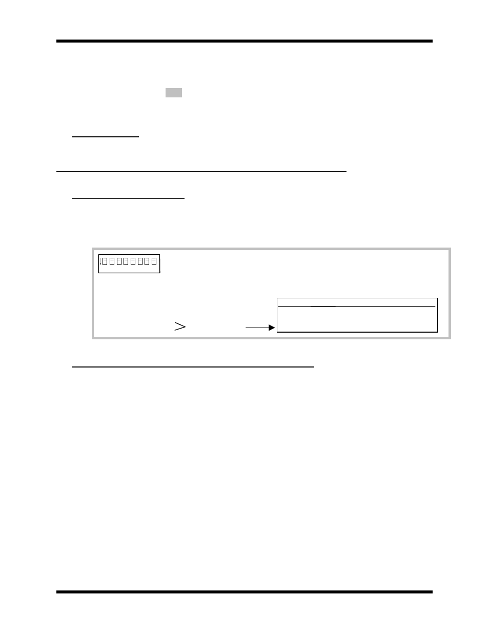
A) Select an Ethernet connector:
• OPTION switches are used to select the active Ethernet connector. Use the 10BaseT setting for the
NCB-Etherlon and the AUI setting for the NCB-Fiberlon. The position of the OPTION switches
are read by the NCB module at power-up or after pressing the “RESET” button on the front panel.
1
2
3
4
5
6
7
8
ON
1. Not Used
2. Not Used
3. Not Used
4. Not Used
5. Not Used
6. Not Used
7.
8.
Modem Mode
Switch:
7
8
10BaseT
UP
UP
AUI (Fiber)
DN
DN
X = Don’t Care
Ethernet Connector
B) Mount the NCB units (See Appendix B for Mounting Option details):
Desk, Wall, or Rack Mounting
• Non-slip rubber feet are included on all NCB modules to allow them to conveniently rest on any
horizontal surface. Four 6-32 threaded holes are also available on the bottom of the module to
allow bolting of the module in any convenient orientation. WARNING: Care should be taken to
limit protrusion of the screw into the module to no more than 0.125 inch from the module
bottom surface!
• Mounting kits are available as options to allow wall or rack (19” EIA) mounting of the NCB
module.