Grounding, Lonworks network connection, Ethernet connection – CTI Products NCB/FL with Fiber Interface User Manual
Page 18: Dc power connection
CTI Products, Inc.
NCB-EL/FL User Guide
2. Installation
15
C) Make electrical connections (See Appendix C for connector details):
Grounding
• When wall or rack mounting the NCB, a suitable safety and protective earth ground should be
provided to the metal enclosure. The protective earth ground provides a path to ground for
electrostatic discharge (ESD) energy. This connection is most conveniently made directly to the
wall mount bracket or rack plate.
L
ON
W
ORKS
Network Connection
• The local L
ON
W
ORKS
network must be attached to the NCB module via the “NETWORK”
connector following standard Echelon guidelines as to cable type, cable length, and termination
appropriate for the selected transceiver.
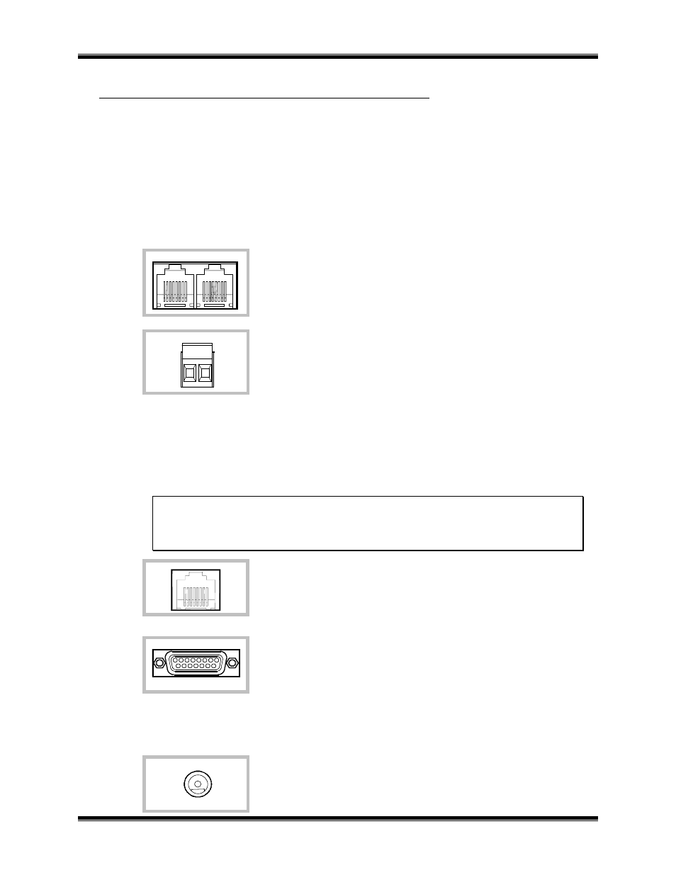
The dual RJ-45 NETWORK connector allows a daisy-chained network
connection method, as the network pins of the two RJ-45 connectors are
directly paralleled.
The 2 pin removable terminal strip is wired in parallel with the network
connections on the dual RJ-45 connector.
NOTE: If your NCB module was purchased without a
L
ON
W
ORKS
transceiver (SMX-ready), refer to Technical Note TN025 to install
your SMX transceiver.
Ethernet Connection
• The Ethernet network must be attached to the NCB module via one of the Ethernet connectors. Be
sure to set the OPTION switch positions 7 and 8 as shown in Step 6A to match the type of Ethernet
physical media being used.
WARNING: DO NOT connect the NCB modules to a live Ethernet network until they have
been reconfigured with IP parameters supplied by the Network Administrator. Network-wide
problems could arise from connecting devices to a network without coordination of
addressing information.
The 10BaseT port utilizes a standard RJ-45 connector. Level 5
unshielded twisted pair cable should be used between the NCB-Etherlon
module and the hub. The length of this cable should be less than 100
meters (328 feet).
The AUI port accepts standard Ethernet MAUs (Media Attachment Units)
for 10BaseFL (fiber) and 10Base5 (“thicknet”).
DC Power Connection
DC power must be attached to the NCB module via the DC IN connector.
Apply DC power to the NCB module only after all other connections
have been made. A wall plug-in style power supply designed for the
NCB module is an available option.
NETWORK
OUT
IN
NETWORK
10BASE-T
DC IN
AUI