Front panel, Mcn network note 1, Mcn network note 2 – CTI Products HIB-IP IP Interface User Manual
Page 7: Front panel indicators – additional information, Mcn network connections, Reset button, Csvc button identifies control processor, Ront, Anel, Figure 2 hib-ip front pane
CTI Products, Inc.
HIB-IP & HIB-IP 8000 Hardware Reference Manual
1. Introduction
7
F
RONT
P
ANEL
1
2
3
4
5
9
8
7
6
ERR
ACT
PWR
RESET
WINK
ETH RX
ETH TX
CSVC
RSVC
NETWORK
OUT
IN
ASYNC
NETWORK
NCB
NETWORK COMBINER
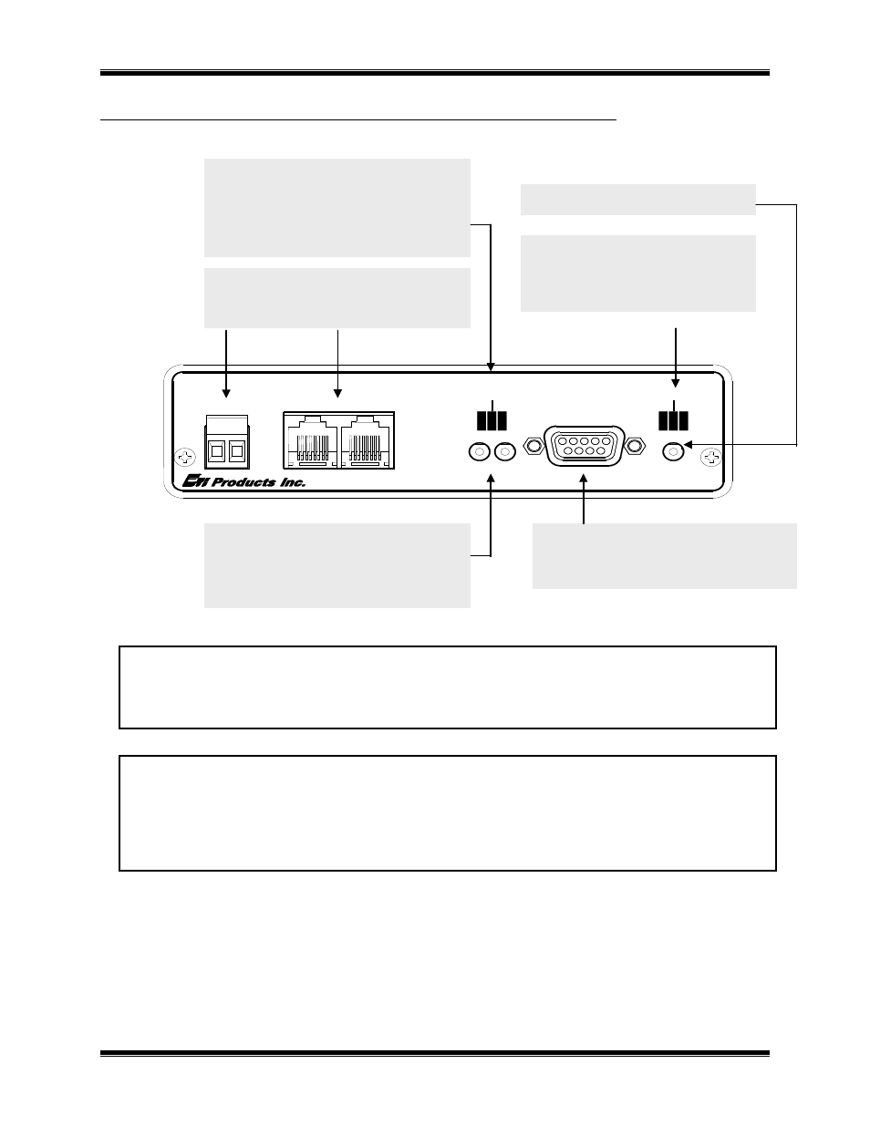
Figure 2 HIB-IP Front Pane
MCN Network Note 1
Unlike most other MCN modules, the HIB-IP does not inject power into the Network Out connector. It also
does not use any DC power from the Network In connector. All 8 pins on the Network In & Out connectors are
paralleled, so that any power from other modules will be passed through.
MCN Network Note 2
Although the MCN Network connectors are RJ-45s, THEY ARE NOT ETHERNET CONNECTORS. Because
the MCN network connectors on the front of the units may have DC power on them from other MCN devices,
DO NOT CONNECT THE NETWORK IN OR OUT CONNECTORS TO ETHERNET PORTS. THIS CAN
DAMAGE THE ETHERNET DEVICE. The Ethernet cable should be connected to the 10BASE-T connector on
the rear of the HIB-IP unit.
Front Panel Indicators – Additional Information
ETH RX LED (Yellow) – Indicates when a packet has been detected on the Ethernet port. NOTE: Flashing of
this LED does NOT necessarily mean that a packet addressed to this HIB-IP module has been received, just that
a packet has been detected on the Ethernet network.
ERR LED (Red) – Indicates a possible error condition. See Table E2 in Appendix E for a list of Error Code
definitions.
ETH TX LED Indicates when a packet has been
transmitted on the Ethernet port
WINK LED
Normally not used.
May be winked during Custom
Configuration to identify a unit.
ETH RX LED Indicates when a packet has been
detected on the Ethernet port
MCN NETWORK Connections
RJ-45 Normal Network connection.
Screw Terminals not normally used.
*** See MCN Network Notes 1 & 2***
Async Serial Programming Connector
Used with PC running MCNConfig
to access IP address parameters
RESET Button
Buttons for use with Custom
Configuration
Press only when requested.
CSVC Button Identifies Control Processor
RSVC Button Not used
PWR LED Indicates correct input power
ERR LED
Indicates an error condition
(see below and Appendix D)
ACT LED
Indicates that a PC has
connected to the HIB-IP.