Wall mount option, Figure 6 hib-ip module wall mounting, Etl appro – CTI Products HIB-IP IP Interface User Manual
Page 22
CTI Products, Inc.
HIB-IP & HIB-IP 8000 Hardware Reference Manual
Appendix B. Mounting Options
22
Wall Mount Option
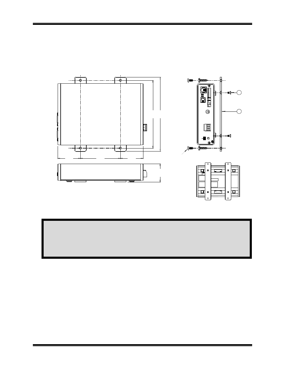
The wall mount option allows an HIB-IP module to be mounted to any flat surface. The HIB-IP module has
four screw holes on the bottom. Simply attach the two mounting plates to the bottom of the module using the
four flat-head screws provided with the wall mount kit. This assembly is then attached to the flat surface with
user-provided fasteners. Figure 6 shows a dimensioned view of the wall mount installation.
Industry
Canada
NOTE:
THE NUMBERS ON THIS DRAWING REFER TO THE ITEM NUMBERS
ON THE CORRESPONDING BILLS OF MATERIAL FOR THIS ASSEMBLY.
24 VDC
100 mA
BOTTOM VIEW
USE
ONL
Y 6-3
2 X
1/4"
L
ONG
FLA
T H
EAD
S
CRE
WS
TO AT
TAC
H T
HE
WAL
L M
OU
NT BR
ACKE
T T
O T
HIS
UN
IT
.
TO
PRE
VE
NT DAM
AGE
TO
T
HE CI
RCUI
T BO
ARD.
CAU
TIO
N!
USE ONLY 6-32 X 1/4" LONG
FLAT HEAD SCREWS TO ATTACH THE
WALL MOUNT BRACKET TO THIS UNIT.
TO PREVENT DAMAGE TO THE CIRCUIT BOARD.
CAUTION!
ETL APPRO
3.500
1.980
6.
1
30
6.
7
00
1.
6
42
TOP VIEW
1
2
Provided by installer.
A
ll
ow
r
oom
on
end
s
for
c
on
nec
to
rs
.
A
ll
ow
r
oom
on
end
s
for
c
on
nec
to
rs
.
SIDE VIEW
1.980
QTY 2
QTY 4
QTY 4 NO. 8 SCREWS OR OTHER
APPROPRIATE HARDWARE.
OR
OR
1
2
3
4
5
6
7
8
O
N
OP
T
ION
A
D
C
IN
ER
R
AC
T
PW
R
R
SVC
C
SVC
A
UDI
O
L
IN
E
CD
OH
R
ES
ET
CM
D
NCB
N
ET
W
O
R
K C
O
M
BI
N
ER
NE
T
W
O
RK
Figure 6 HIB-IP Module Wall Mounting
CAUTION
Be sure to use the flat head screws provided with the wall mount kit. If you are not using the wall mount
kit from CTI Products, Inc., make sure that the screws do not protrude into the enclosure more than 0.125
inches from the bottom surface of the module.
Using a longer screw that touches the PC board inside the module may damage the module. Doing so will
void the unit’s warranty.