D) connect to the mcn & ip networks, Mcn network connection, Ethernet connection – CTI Products HIB-IP IP Interface User Manual
Page 15
CTI Products, Inc.
HIB-IP & HIB-IP 8000 Hardware Reference Manual
3
Installation
15
-
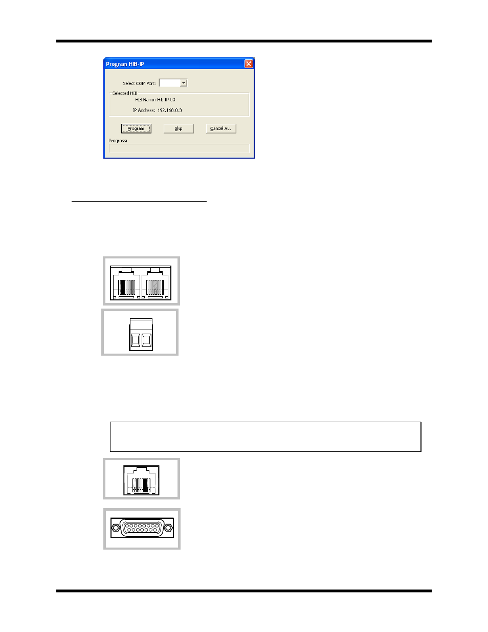
Select the proper COM port and hit "Program".
D) Connect to the MCN & IP networks:
MCN Network Connection
• The local MCN network must be attached to the HIB-IP module via the “NETWORK” connector
following standard guidelines as to cable type, cable length, and termination appropriate for the
selected transceiver.
The dual RJ45 NETWORK connector allows a daisy-chained network
connection method, as the network pins of the two RJ45 connectors are
directly paralleled. The HIB-IP unit does not inject DC power on the
network cable. It does not use any DC power from the cable.
The 2 pin removable terminal strip is wired in parallel with the network
connections on the dual RJ45 connector. This connector is normally not
used.
Ethernet Connection
• The Ethernet network must be attached to the HIB-IP module via the Ethernet 10Base-T connector
on the rear of the unit.
WARNING: DO NOT connect the HIB-IP module to a live Ethernet network until it has been
reconfigured with its IP parameters. Network-wide problems could arise from connecting
devices to a network without coordination of addressing information.
The 10BaseT port utilizes a standard RJ45 connector. Level 5 unshielded
twisted pair cable should be used between the HIB-IP module and the IP
switch or hub. The length of this cable should be less than 100 meters (328
feet).
An AUI connector was present on early units,
This connector has been removed on later versions.
It was not used for HIB-IP applications.
10BASE-T
AUI
NETWORK
OUT
IN
NETWORK