Inputs – CONTREX CX-1010 User Manual
Page 39
Page 37
INPUTS
NOTE: Refer to pages 9 and 35 before you begin wiring.
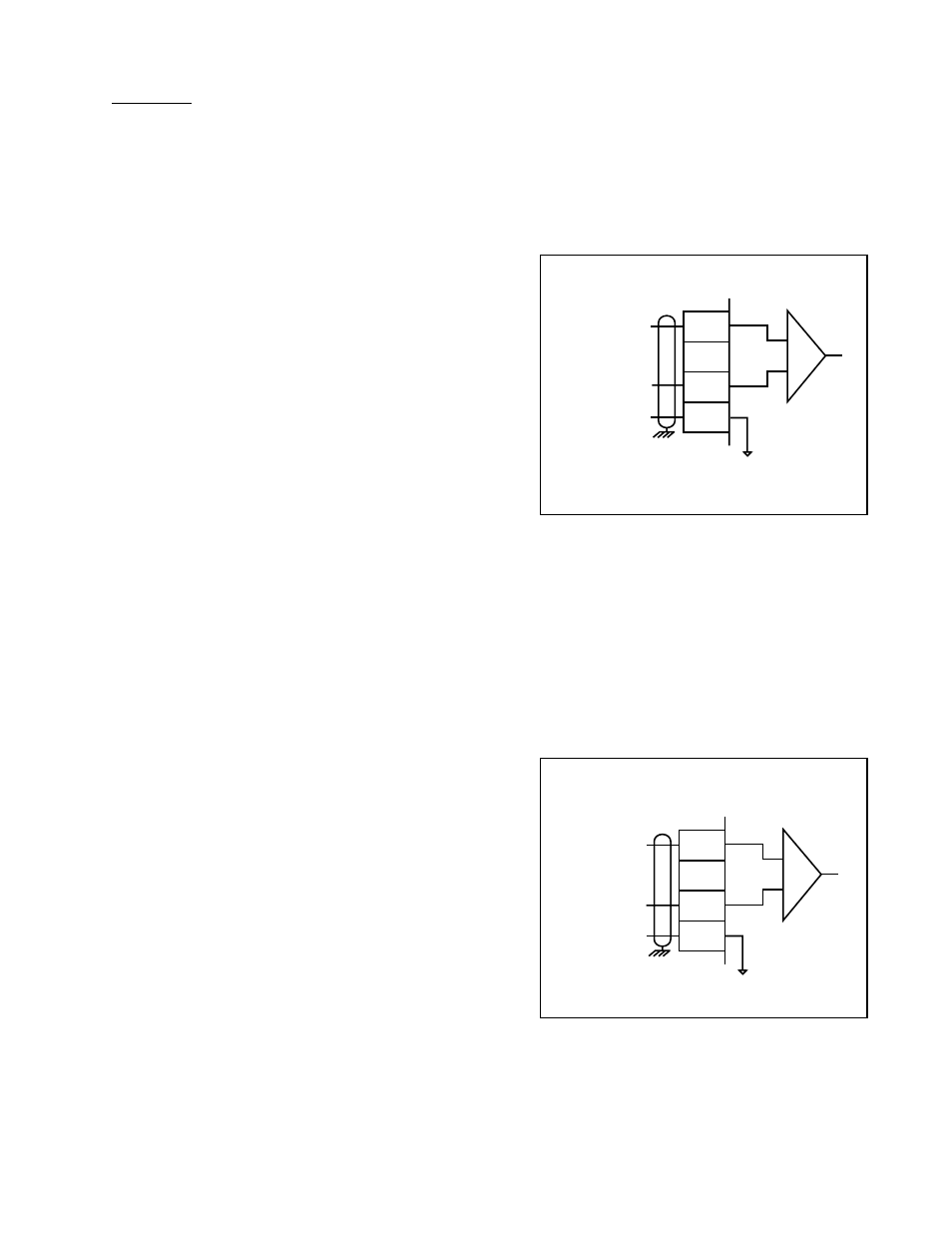
Figure 36 Analog Input 2: Voltage
Input
Figure 35 Analog Input 1: Voltage Input
5
6
7
8
JA
±
12V Input
—
Common
+
+
–
2
3
4
8
JA
±
12V Input
—
Common
+
+
–
Analog Input 1:
Voltage Input Wiring
(JA, Pins 2, 4, 8)
The Analog Input 1 can be used with either
±
12 VDC or
0-20 mA inputs. Figure 35 displays the
±
12 VDC option.
For the differential inputs:
Connect JA pin 2 to the positive differential signal
source.
Connect JA pin 4 to the negative differential signal
source.
Connect JA pin 8 to the common of the differential
signal source.
For the non-differential inputs:
Connect JA pin 2 to the signal voltage source.
Connect JA pin 4 and JA pin 8 to the common of the
signal source.
Analog Input 2:
Voltage Input Wiring
(JA, Pins 5, 7, 8)
The Analog Input 2 can be used with either
±
12 VDC or
0-20 mA inputs. Figure 36 displays the
±
12 VDC option.
For the differential inputs:
Connect JA pin 5 to the positive differential signal
source.
Connect JA pin 7 to the negative differential signal
source.
Connect JA pin 8 to the common of the differential
signal source.
For the non-differential inputs:
Connect JA pin 5 to the signal voltage source.
Connect JA pin 7 and JA pin 8 to the common of the
signal source