Operating instructions – CM-ET Prostar User Manual
Page 6
5
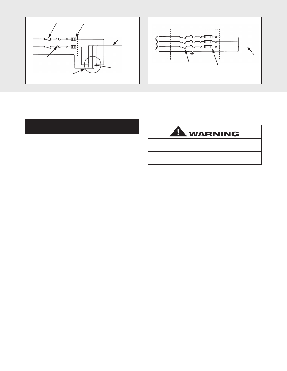
Hoist Power
Cord
Green-Yellow
* Manual
Disconnect
Switch
Black
White
Ground
* Slow Blow Fuses
or Inverse Time
Circuit Breakers
* Thermal
Overload
Relay
*Receptacle Rated for 15 Amps Minimum (220-1-50 units do not
include Power Cord Plug). Wire Blue and Brown Wires to Fuses or
Circuit Breakers and Green-Yellow Wire to Ground.
Brown
Blue
S
Siin
ng
glle
e P
Ph
ha
as
se
e S
Sy
ys
st
te
em
ms
s
Hoist Power Cord
* Slow Blow Fuses
or Inverse Time
Circuit Breakers
* Must be per National Electrical
Code and These Devices are to be
Supplied by the User.
* Manual Disconnect
Switch
Black
Grey
Brown
Green-Yellow
T
Th
hr
re
ee
e P
Ph
ha
as
se
e S
Sy
ys
st
te
em
ms
s
L1
L2
L3
Ground
In
c
o
m
in
g
P
o
w
e
r
Figure 4A
Figure 4B
CHAIN CONTAINER
If the chain container is to be used, attach it to the hoist per
the instructions provided.
The hoist is equipped with a Protector™ that is designed to
allow the first gear to slip on an excessive overload. An
overload is indicated when the hoist speed slows down, it
raises the load in a jerky manner or it will not lift the load at
all. Also, some clutching noise may be heard if the hoist is
loaded beyond rated capacity. Should this occur, immediately
release the UP button to stop the operation of the hoist. At
this point, the load should be reduced to the rated capacity
or the hoist should be replaced with one of the proper
capacity. When the excessive load is removed, normal hoist
operation is automatically restored.
CAUTION: The Protector™ is susceptible to overheating
and wear when slipped for extended periods. Under no
circumstance should the Protector be allowed to slip for
more than a few seconds.
Due to the above, the hoist is not recommended for use in
any application where there is a possibility of adding to an
already suspended load to the point of overload. This
includes dumbwaiter installations, containers that are loaded
in mid-air, etc. Also, if the hoist is used at unusual extremes
of ambient temperatures, above 150º F (65ºC). or below 15ºF
(-9ºC)., changes in lubricant properties may permit the hoist
to raise larger loads than under normal operating conditions
and present possibility of damage or injury.
On units without contactor (hoists with orange control
station) it is necessary to stop the hoist before changing
direction. Therefore, when lowering a load, the push
button in the control station must be released
momentarily before the UP button is depressed to raise
the load. If this is not done, the hoist will continue to
operate in the down direction while the UP push button
is depressed, and it will continue to lower the load until
the control push button is released. As a result, the
direction must not be reversed quickly (plug reversed).
There are no electrical switches to stop the operation of the
hoist at the upper and lower limits of lift. As a result, it is
necessary to release the push button in the control station to
stop the hoist before the hook block or chain stop contacts
the bottom of the hoist frame. If the hook block or chain stop
contacts the hoist frame, the Protector will function to stop
the hoisting or lowering operation and protect the hoist
components from damage. However, continued, prolonged
or repeated slipping of the Protector will damage the
Protector and cause overheating of the internal hoist
components.
Hoist operation is controlled by depressing the control
station push buttons (Refer to Figure 5A, pg 6). Depressing
the UP push button will move the load hook toward the hoist
head; depressing the DOWN push button will move the load
hook away from the hoist head.
The UP and DOWN buttons are momentary type and the
hoist will operate in the selected direction as long as the
button is held in the depressed position. Release the push
button and the hoist will stop.
It is preferred that the load always be tied off with auxiliary
chains or cables before access to the area beneath the load
is permitted. As an alternative, the system may be designed
such that malfunction or failure of one hoist’s load bearing
components does not cause load loss and/or overloading of
any other hoists in the system. Note that in such a system,
hoist performance and function must be monitored visually
or with the use of load cells. Check the supporting structure
to which the load hook is to be attached. Make sure the
attachment point as well as the structure have sufficient
strength to withstand several times the load imposed. If in
doubt, consult a registered engineer and local building
codes.
Allowing the hook block to run into the hoist when raising a load or
allowing the chain stop to run into the hoist when lowering a load
may break the chain and allow the load to drop.
TO AVOID INJURY:
Do not allow the hook block or the chain stop to contact the hoist
frame.
OPERATING INSTRUCTIONS