Installation – CM-ET Prostar User Manual
Page 4
BC Series Beam Clamps
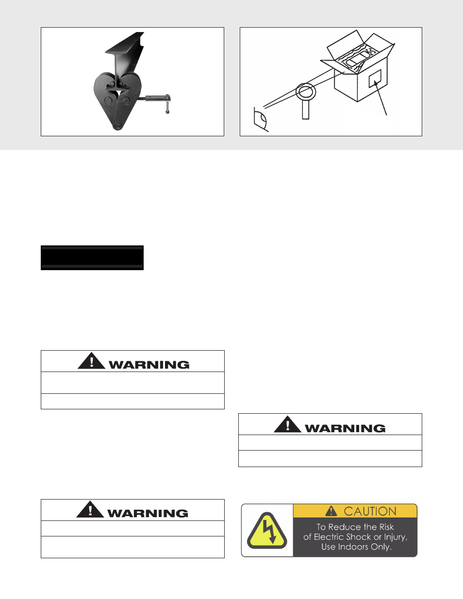
The beam clamps are ideal as anchors for rigging
applications (Figure 2A). The BC series clamps can be
adjusted to fit a wide range of beam sizes. The lightweight
and compact design makes the beam clamps ideal for
repeated set-ups and tear-downs.
Entertainment Rigging Products
Refer to sales Bulletin No. EPD-10B for additional rigging
products that can be used in the entertainment industry.
UNPACKING
After opening the carton (Figure 2B) , carefully inspect the
hoist frame, cords, hooks, chain and control station for
damage that may have occurred during shipment. If there is
damage, refer to the packing slip envelope.
Make sure that the power supply (Figure 3A) to which the
hoist is to be connected is the same as that shown on the
identification plate located on bottom of hoist.
MOUNTING THE HOIST
Attach the hoist to the truss/structure to be lifted using the
mounting hook (Figure 3B) . Be sure that the attachment
point is held in the lowermost part of the hook arc and the
latch is tightly against the hook tip. Also, the attachment
point must have sufficient strength to withstand several times
the load imposed. If in doubt, consult a registered engineer
and local building codes.
3
Operating a unit with obvious external damage may cause load to
drop and that may result in personal injury and/or property
damage.
TO AVOID INJURY:
Carefully check unit for external damage prior to installation.
Figure 2A
Figure 2B
Claim Procedure
POWER SUPPLY SYSTEM
(Refer to Figure 4A or 4B on page 5). To insure proper
operation, to avoid damage to hoist and electrical system
and to reduce the risk of electric shock or fire, the branch
circuit supplying power to the hoist must:
1. Have ample capacity to prevent excessive voltage drop
during starting and operation (refer to “Checking for
Adequate Voltage at Hoist” on page 4). When determining
the size of branch circuit components and conductors,
special consideration should be given to the starting
current-amps (approximately three times that shown on
the hoist identification plate) and the length of the
conductors. As a minimum, the system should be rated for
15 amps and it should have #16 AWG, or larger, wiring.
2. Be in accordance with the National Electrical Code
(ANSI/NFPA-70) and applicable National, State and Local
Codes.
3. Effectively ground the hoist in accordance with National
Electrical Code and other applicable codes. Proper
grounding provides a path of least resistance for electric
current to reduce the risk of electric shock. The power
cord of the hoist includes a green-yellow wire for
grounding the hoist to the external power supply system.
Be sure that the receptacle opening that receives the
longest prong is properly grounded. If grounding is to be
through the trolley trackwheels, each section of the
runway must be grounded to the building ground system
using metal to metal connections.
4. Include slow blow type fuses or inverse trip time circuit
breakers to permit the hoist to start and accelerate load.
5. Include a disconnecting means capable of being locked
in the “open” position.
An inadequate attachment point may allow the hoist and load to
fall and cause injury and/or property damage.
TO AVOID INJURY:
Make sure the attachment point has sufficient strength to hold
several times the hoist and its rated load.
Failure to properly ground the hoist presents the danger of electric
shock.
TO AVOID INJURY:
Permanently ground the hoist as instructed in this manual.
INSTALLATION