Cashco 521 User Manual
Page 9
IOM-521
9
and align ment of parts (10) (8) (11) (7),
re move temporary spacer while continu-
ing downward force on the stem (9) while
si mul ta neous ly holding the bonnet (2) from
drop ping down wards.
13. Lower bonnet (2) carefully downwards into
the recess of the body sub-assembly (1)
while con tin u al ly applying downward force
on the stem (9).
14. At this point, downward force on stem (9)
may be exchanged for down ward force on
the bon net (2). Hand-tighten all bonnet cap
screws (14); relax down ward force on bonnet
once cap screws have taken up all slack.
15. Using a torque wrench, tight en bonnet cap
screws (14) in alternating cross-pat tern in
1/4 rev o lu tion in cre ments to 40 ft-# (55 N-M).
7. Center the loose parts (10) (7) surrounding
the stem (9) as close as possible.
8. Position the bonnet (2) over the exposed
upper stem sub-assembly (9), ensuring
that the anti-rotation "stop" (square or fl at
surface of the stem) is properly en gaged
into the bonnet (2) square recess.
9. Place a temporary spacer device (screw-
driv er blade, nuts, plain washers, etc.)
equallyspaced on the body (1) fl ange to hold
the bonnet (2) up, as bonnet is lowered into
the body, maximizing the gap between the
bonnet fl ang es (1) (2).
10. Place anti-seize thread lubricant on bonnet
cap screws (14). Engage all bonnet cap
screws (14) with lockwashers (13) ap prox i-
mate ly 1-1/2 revolutions.
11. Visually observing the gap between the
bon net (2) lower fl ange surface and the
body sub-assembly (1) bon net fl ange, ap-
ply downward force tend ing to seat the plug
end (3). This will pull the bellows (8.1) into
proper position for the primary bon net seal.
12. When visually satisfi ed of concentricity
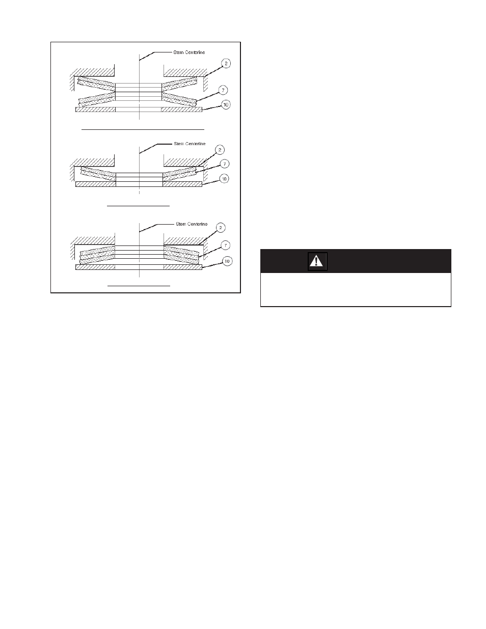
Figure 7: Belleville Spring Washer Orientation
1/2" (DN 15) & 1-1/2" (DN 40) Body Sizes
1" (DN 25) Body Size
2" (DN 50) Body Size
CAUTION
Improper bonnet bolting torques may lead to
premature failure of the primary and secondary
bonnet seals.
16. Engage threaded, vented pipe plug (12) into
the 1/8" NPT tap on the bon net (2) if it was
removed. If a lubricating oil is compatible with
the fl uid, a light coat ing will aid in pre vent ing
galling of the plug (12). En sure that the tip
of the notch on the threads is in the bonnet
(2) at least 1-1⁄2 revolutions. Do not over-
tighten to min i mize chanc es of galling.
Do not use thread sealing com pound that
might “fi ll in” the notch and negate the pur-
pose of the notch.
17. The packing ring set (6) de sign is identical
for all unit body sizes. It consists of seven
V-rings (6.1) and one each male (6.2) and
female (6.3) adapter. (See Figure 8.)
The
purpose of the packing rings (6) is to mini-
mize moisture ingress, and to serve as a
sec ond ary stem seal in the event of bellows
sub-as sem bly (8) failure.
Carefully install rings (6) as indicated in
Fig ure 8, one at a time, using a hollow tool
to press the rings (6) to their fi nal position.
Take care in slipping the rings (6) over the
threaded end of the stem (9) so as to not
mar the ring’s (6) internal surfaces. Do not
reverse ori en ta tion for vacuum service. Do
not “split” rings (6) for ease in replacement.
Do not reuse re moved packing rings (6).