Cashco 521 User Manual
Page 5
IOM-521
5
A. General:
1. Once
fl uid pressure has been iso lat ed by
block valves, and piping fl ange bolting has
been only loos ened, care ful ly re move vented
pipe plug (12) from the bonnet (2), applying
the detection procedures of C. 1. above, as
a small quantity of fl uid may be “trapped” in
the void space of the bellows (8) interior due
to permeation. The plug (12) has a “groove”
notched in its threads to assure venting prior
to the threads fully disengaging. Once fully
vented and/or purged as required by safety
procedures, reinstall the plug (12) using a
fl uid compatible lubricant . DO NOT USE
THREAD SEAL ANT FOR VENT ED PIPE
PLUG (12) ON RE IN STAL LA TION.
2. Maintenance procedures hereinafter are
based upon removal of the valve/actuator
unit from the pipeline where installed.
3. Owner should refer to Owner’s procedures
for re mov al, handling and cleaning of non-
reuseable parts and suitable sol vents, etc.
4. Valves supplied from the factory do not use
any sealing aids for the gasket such as oil,
sealant, or pipe dope in the wetted portions
of the valve body as sem bly. Sealing aids
should not be required and are not rec om-
mend ed.
5. All indicated Item Numbers that are with
re spect to actuator assembly (AA) will be in
pa ren the sis and un der scored; i.e. (20). All
Item Num bers that are with respect to the
body assembly (BA) are not underscored;
i.e. (32). Reference with respect to the
positioner is in double parentheses; i.e.
((AP)).
V. MAINTENANCE
WARNING
Model 521 control valves fre quent ly are installed
in haz ard ous/le thal fl uid ser vic es. Be fore re mov al
from pipe line or any level of dis as sem bly, con sult
the Own er’s safety pro ce dures for proper fl ushing,
clean ing and han dling of a valve ex posed to po-
ten tial ly haz ard ous fl uids dur ing de-pres sur iza tion
and re mov al. Owner's safe ty procedures pre empt
any state ments or rec om men da tions con tained in
this IOM.
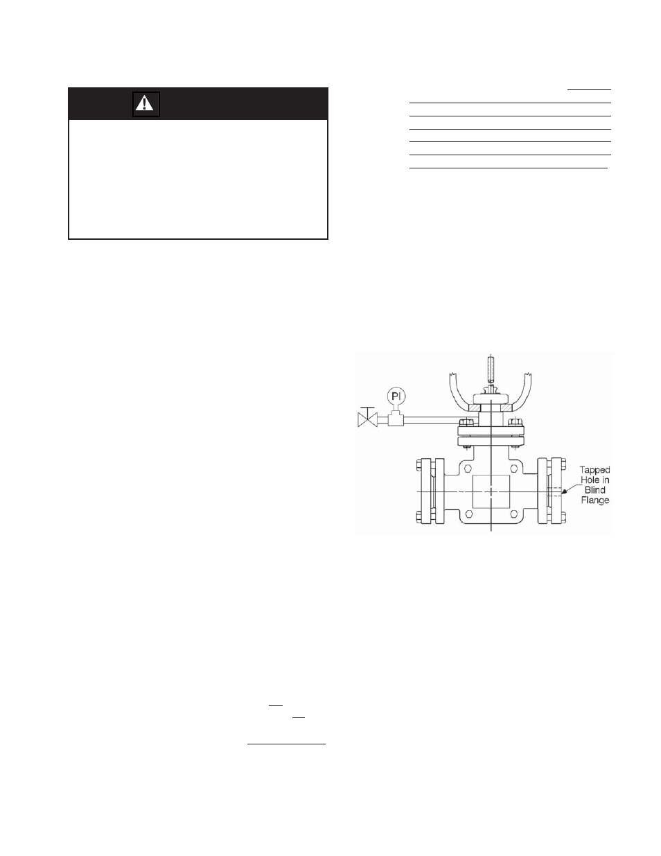
Figure 5: Pressure Boundry Testing Confi guration
SECTION V
6. The stem sub-assembly (9) is designed
for non-rotation when installed. DO NOT
AT TEMPT TO RO TATE WITH THE STEM
SUB-ASSEMBLY IN STALLED; FAILURE
TO HEED MAY CAUSE DAMAGE TO THE
STEM SUB-ASSEMBLY (9), THE BEL-
LOWS SUB-AS SEM BLY (8), THE PLUG
(3) AND/OR THE BODY ASSEMBLY(1).
Exhibit special care when handling the stem
(9) sur face where it contacts the packing
(6).
B. Pressure Boundary Leakage Shop Test:
1. Secure the body assembly (BA) in a vise
with the valve stem (9) oriented vertically.
2. Remove vented pipe plug (12).
3. Install a pipe nipple, test pressure gauge and
isolation valve into the 1/8"-NPT (female)
open ing. (See Figure 5.)
4. Place a suitable adhesive tape (“duct tape”)
around the perimeter of the bonnet/body
fl ange. Place tape on the “joint lines” of the
shell halves (1.1) (see Figure 10). Place blind
fl ang es over the fl anged end connections
and bolt down; one of the blind fl anges must
have a hole thru the face; place tape over
the opening of the blind fl ange.
5. Using a source of acceptable fl uid such as
ni tro gen gas, pressurize the bellows “void
zone” to 30 psig (2.1 Barg). Tightly close off
the isolation valve of 3. above. Disconnect
the pressure source.
6. Poke small holes in the tape at the bonnet/
body fl ange and at the opening in the blind
fl ange.