Cashco 521 User Manual
Page 10
IOM-521
10
4. This procedure assumes that bonnet (2) has
been bolted to the body sub-assembly (1).
5. Engage stem jam nut (20) to body as sem-
bly’s stem (9) by rotating CW (viewed from
valve stem (9) end). Rotate jam nut (20) all
the way to root of the stem (9) threads.
6. Lower actuator assembly (AA) until the
open ing of the actuator yoke (1) is at the
level of jam nut (20).
7. Place yoke nut (15) over valve stem (9) and
lower the nut to rest upon the yoke (3).
8. Push valve stem (9) downward towards
seat ing po si tion. NOTE: The valve bellows
(8) may give “spring action” to keep the plug
(3) par tial ly away from the seat.
9. For Direct Action ATO-FC Only: Connect
a temporary air supply hose that has an
adjustable airset with gauge connected at
the lower actuator inlet. Pressurize actuator
to a suffi cient level to the upper pressure
level of the bench setting; i.e. for 5–15 psig
(.34–1.03 Barg) range, set pres sure at 15
psig (1.03 Barg).
10. Apply Loctite Nickel Anti-Seize to grove and
top surface of swivel lower knuckle. Engage
(slide) the lower knuckle (44) into the upper
knuckle (43) saddle.
11. Continue lowering the actuator assembly
(AA) until the swivel lower knuckle (44)
connector and the valve's stem (9) just
touch. NOTE: For ATO-FC may need to
slowly reduce air pressure in the actuator
to connect the stem and knucle.
12. Thread
yoke
nut (15) onto bonnet (2) threads
by hand as far as possible to help stabilize
topworks. Wrench-tight en one-half (1/2)
extra revolution.
13. Engage valve stem (9) threads to swiv el
lower knuckle (44). Rotate swivel knuckle
(44) CW (viewed from actuator end) to
engage with valve stem (9), refer to V.C.
Steps 9A or 9B for the number of rev o lutions
recorded to dis-engage the lower knuckle.
14. Remove overhead rigging to allow ac tu a tor
assembly (AA) to fully rest on the bonnet (2).
Refer back to V.C. Step 2 for alignment of
match marks. Hand-tighten yoke nut (15).
18. Place anti-seize thread lubricant on threads
of packing gland nut (5). Place gland nut
(5) over the stem (9) end and engage with
the bonnet (2) by rotating CW (viewed from
ex posed stem (9) end); continue fi nger-
tight en ing to the point of resistance. Wrench
tighten gland nut (5) 1/8 revolution past the
manual tightening re sis tance point.
19. Place bonnet spacer (19) down over
threaded portion of the bonnet (2).
20. Valve body assembly (BA) is completed, and
may be pressure tested up to 275 psig x 1.5
= 413 psig (19.0 Barg x 1.5 = 28.5 Barg) at
ambient tem per a ture. Before pressurizing
for hydro, ensure that plug (3) is away from
body (1) seat. NOTE: Use soft gas kets on
body as sem bly (BA) end fl anges to prevent
dis tor tion of TFE fl ange fac ings.
H. Mounting Actuator Assembly to Body
Assembly:
1. Reference Actuator IOM-C27-C53 for item
number call outs and drawings for actuator.
This procedure assumes that accessory
plate ((AP)) or indicating washer (51) was
not removed or has been secured to the
actuator stem(6) by the swivel upper knuckle
(43) - tighten with 20-30 ft.lbs. (27-40 N M).
DO NOT allow actuator stem (6) to rotate.
Secure fl ats on bottom of stem (6) when
rotating knuckle (43).
2. Secure the body as sem bly (BA) in a vise
with the valve stem (9) oriented vertically.
3. Rig actuator assembly (AA) to be supported
from above.
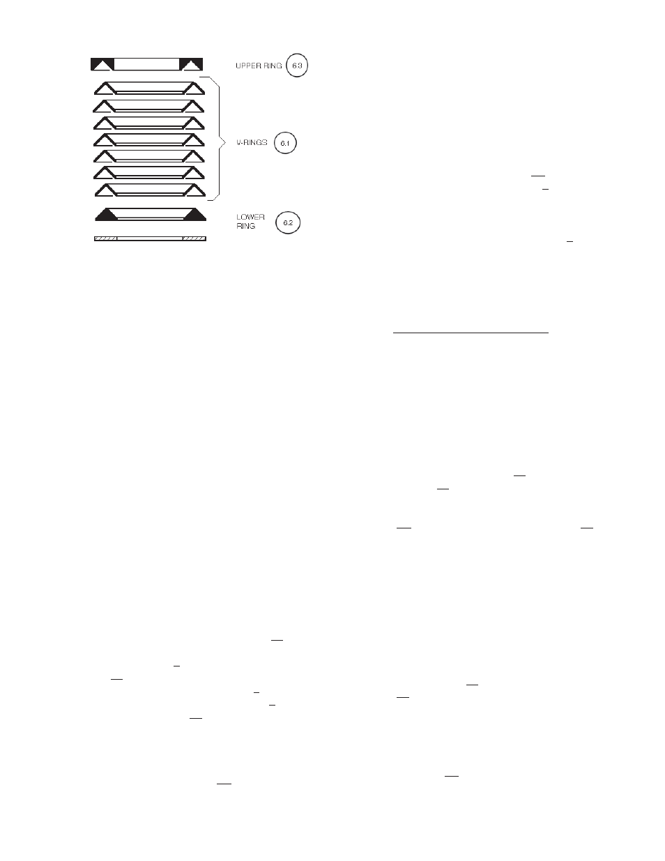
Figure 8: Packing Ring Set