Cashco 521 User Manual
Page 2
IOM-521
2
III. INSTALLATION
A. Orientation
1. Recommended orientation when installed is
in a hor i zon tal pipeline with the stem verti-
cal. Valves may be installed in a vertical or
hor i zon tal pipeline with the stem between
vertical and horizontal.
2. Outdoors, all installations may be oriented
at any angle from horizontal-to-vertical, as
per A.1. above.
3. Model 521 valves should not be installed
with the stem oriented below horizontal/
down wards.
4. In no case is additional weight to be applied
to the actuator assembly when installed in
an ori en ta tion other than vertical.
8. Undue piping stress/strain or bending
torques may not be transmitted thru the
control valve body. One pipe (inlet or outlet)
should be anchored rigidly for piping that
is “hot” or “cold” with respect to ambient
SECTION III
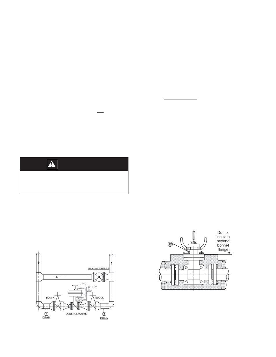
Figure 2: Body Insulation
B.
Piping
System
1. It is recommended that the control valve unit
be installed with a double-block and bypass
as indicated in Figure 1. This arrangement
is recommended especially where main te-
nance will be done on the valve body while
still installed in the pipeline.
2. If pipe reducers are located before and/or
after the valve body, keep the reducers as
close as practical to the valve body; this is
especially important where the reducers are
more than one line size larger than the valve
body size, which is common in gaseous
ser vice.
3. Clean the piping of all foreign debris, in-
cluding chips, weld scale, weld splatter,
oil, grease, sand or dirt prior to installing
the control valve; THIS IS AN ABSOLUTE
REQUIREMENT.
4. Field hydrostatic testing the completed
piping system, including the Model 521,
to 1-1/2 x CWP in di cat ed on Model 521
name plate is ac cept able. If hydro test pres-
sure ex ceeds the 1-1/2 x CWP limit, the 521
must be re moved for such testing. Before
pres sur iza tion, the valve plug should be
lifted from the seat if of re verse, ATO-FC
action.
5. Flow Direction: Install so the fl ow direc-
tion match es the arrow cast on the valve
body.
6. Valves are not to be direct buried un der -
ground.
7. Insulation may be applied as indicated in
Fig ure 2. Drainage from the packing area
must be ensured when fully installed, sealed
and lagged for outdoors installation. Vented
pipe plug (12) should not be covered.
WARNING
The valve/actuator unit should not be used as a
“step” to sup port per son nel. Failure to comply
may cause leak age at the bonnet/body joint, al-
low ing pos si ble con tact with harm ful fl uids.
Figure 1: Typical Control Valve Station