Cashco 521 User Manual
Page 17
IOM-521
17
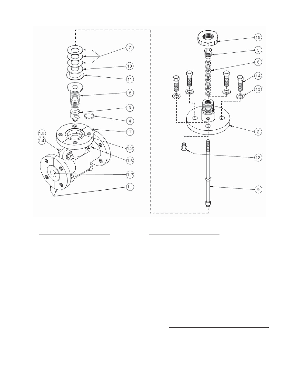
Figure 10: Control Valve Internals
ITEM
NO. DESCRIPTION
1 Body
Sub-Assembly
1.1
* Half Shell
1.2
* TFE Core
1.3
* Cap Screw
1.4
*
Nut
1.5
*
Lockwasher
2 Bonnet
3 Plug
Head
4
Plug Retainer Strip
5
Packing Gland Nut
6 Packing
Set
ITEM
NO. DESCRIPTION
7
Belleville Spring Washer
8 Bellows
Sub-Assembly
9 Stem
Sub-Assembly
10 Spacer
11 Bonnet
Gasket
12
Vented Pipe Plug
13 Lockwasher
14
Bonnet Cap Screw
15 Yoke
nut
Not
Shown
18 Rating
Tag
19 Bonnet
Spacer
20 Jam
Nut
*
Sub-level parts that make up the body sub-assembly; NOTE: DO NOT DISASSEMBLE THE PARTS OF THE
BODY SUB-ASSEMBLY (1)! The valve body (1) is ma chined after the shell halves (1.1) have been bolted (1.3,
1.4, 1.5) around the TFE core (1.2). Dis as sem bly of the body sub-assembly (1) will cre ate align ment problems
upon com plet ed reassembly. The TFE core (1.2) is not replaceable, except as a body sub-as sem bly (1).
NOTE: No. varies
by body size