Cashco 521 User Manual
Page 6
IOM-521
6
6. Loosen stem nut (20) by rotating nut CW
(viewed from above) to base of threads.
7. Loosen packing (6) by turning packing gland
nut (5) CCW 2-3 revolutions.
8. Rotate yoke nut (15) CCW to fully loosen
nut.
9A. For ATO-FC Reverse Action Actuators:
a. Connect a temporary air source
to the actuator and pressurize the
actuator to upper limit of the bench
range specifi ed on the valve name
plate. (Pressure will lift the plug head
(3) away from the body's (1) integral
seat until the plug (3) is 100% open.)
b. Place a wrench on the hex surface of
the swivel lower knuckle (44) and rotate
knuckle CCW (viewed from above ac tu a-
tor) until lower knuckle dis-engages from
stem (9). Keep track of the number of
full rev o lu tions to dis-engage and record
here. _______________
c. Maintain lift support from above the
7. For units with Reverse Action (ATO-FC)
ac tu a tors pressurize to a level suffi cient to
initiate travel to approximately mid-stroke
to hold the plug (3) away from the body (1)
seat.
8. Apply
leak
detection
fl uid to all the potential
leak paths:
a. Packing gland nut (5). (Tighten as nec es-
sary.)
b. Body (1)-to-bonnet (2) fl ange tape hole.
c. Body (1) and bonnet (2) bolting (13, 14,
1.3, 1.4, 1.5).
d. End connection blind fl ange tape hole.
e. Test pressure piping con nec tions.
9. If leakage occurs at:
a. a. above, there is a packing (6) or a pack-
ing (6) /stem sub-assembly (9) failure.
b. b. above, there is a bonnet gasket (11)
failure.
c. c. above, there is a bonnet gasket (11),
or TFE core (1.2) failure.
d. d. above, there is a bellows sub-as sem bly
(8) failure.
10. Following this test procedure may help
to solve main te nance problems when
combined with visual ex am i na tion of disas-
sembled body assembly (BA).
C. Separation of Body/Actuator:
1. Reference the Actuator IOM-C27-C53 for
item number call outs and drawings for
actuator.
2. Secure the body in a vise with the actuator
assembly (AA) oriented vertically. Place
matchmarks between the body (1) bon net
fl ange, the bonnet (2) fl ange, and the yoke
(3) to assist in fi nal ori en ta tion when the
body is dis as sem bled and/or the ac tu a tor
removed. If actuator has handwheel - see
Actuator IOM for removal instructions.
3. Secure and rig the actuator assembly (AA)
for a ver ti cal lift using an overhead hoist.
Remove slack from rigging.
4. This procedure assumes that the body as-
sem bly (BA) has been fully assembled thru
the bonnet (2), including the packing gland
nut (5) and packing (6).
5. Remove vented pipe plug (12) from body.
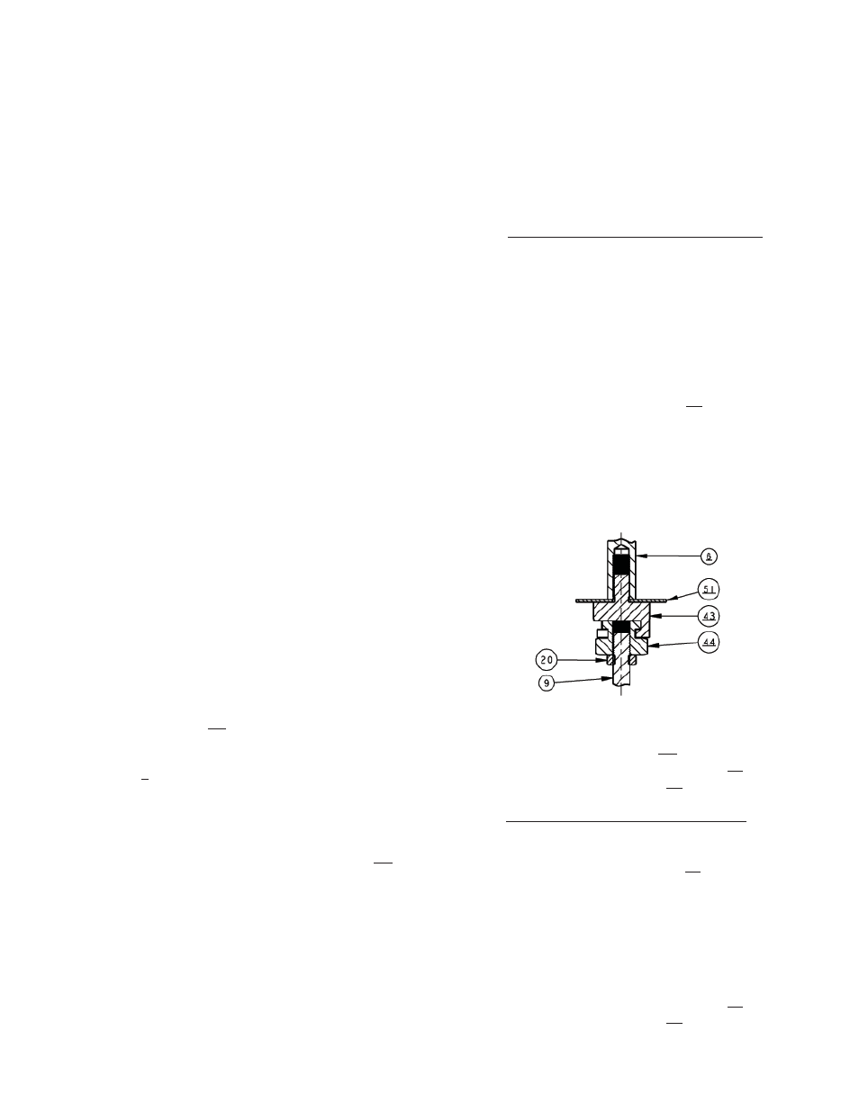
Figure 6: Swivel-Type Connector
actuator assembly (AA). Dis-engage
(slide) the swivel lower knuckle (44) out
of the upper knuckle (43) slot.
9B. For ATC-FO Direct Action Actuators:
a. Place a wrench on the hex surface of
the swivel lower knuckle (44) and rotate
knuckle CCW (viewed from above ac tu a-
tor) until lower knuckle dis-engages from
stem (9). Keep track of the number of
full rev o lu tions to dis-engage and record
here. ________________
b. Maintain lift support from above the
actuator assembly (AA). Dis-engage
(slide) the swivel lower knuckle (44) out
of the upper knuckle (43) slot.