Cashco 964 User Manual
Page 9
IOM-964
9
Number of revolutions to disengage
valve stem from actuator stem:
c. Using soft-jawed pliers, grasp the stem
(3) just below/at the threaded por tion,
and rotate the stem/plug assembly (3)
CCW (viewed from plug end) to re mov al.
Record the num ber of rev o lu tions re quired
to dis en gage in box below:
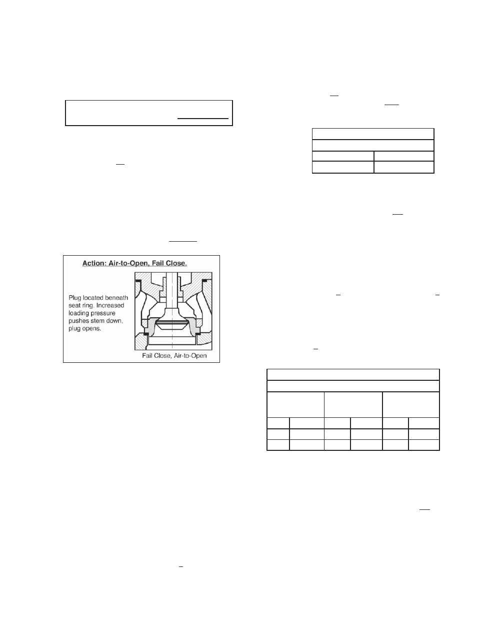
Figure 6: ATO-FC Action
TABLE 1
No. of Stem Revs to Add/Subtract
ATO-FC to ATC-FO
ATC-FO to ATO-FC
+ 6
- 6
d. Partially withdraw the stem/plug as sem bly
(3) from the bonnet (2), taking care not to
drop the seat ring (11), position in di cat ing
disc (20) and ac ces so ry plate ((AP)), if
in stalled.
e. Remove jam nuts (18). Fully with draw stem/
plug as sem bly (3) from the bon net (2).
f. Clean gasket facing sur fac es and in stall
a new seat ring gasket (13) in the body
(1) cavity. Set the seat ring (11) into the
body (1) cavity in an inverted ori en ta tion
from the way re moved.
g. Place a new bonnet gasket (12) in the
body (1) recess.
h. Remove and replace packing rings (6) as
directed else where in this sub-sec tion,
if de sired.
i. Insert the stem/plug assembly (3) back
into the bottom of the bonnet (2). Screw
both jam nuts (18) back onto stem (3),
and locate at the root of the thread por-
tion. Re place all the “loose dan gling”
parts back in their proper order and
ori en ta tion.
NOTE: Reference the IOM for the po si tion er, as
the orientation/location of the ((AP)) may change.
If the action of the po si tion er does not change
when the valve unit’s action is changed, the lo-
ca tion of the po si tion er unit will change from the
right side of the ac tu a tor yoke (1) to the left side,
or vice versa. This requires that the ac tu a tor be
rotated 180 ° from the be gin ning body-to-bon net
ori en ta tion, and that the po si tion er be re moved
and reoriented to an op po site po si tion.
j.
Engage valve stem (3) with the ac tu a tor
stem (19) with the num ber of rev o lu tions
recorded in Step 7.c, plus the num ber
of revs in di cat ed in Table 1.
TABLE 2
ATO-FC CONVERTED TO ATC-FO
Bench Set
Indicated
on Nameplate
New Bench
Set to be
Utilized
Loading
Pres sure for
Step 7.p.
psig
(Barg)
psig
(Barg)
psig
(Barg)
5-15
(.34-1.0)
3-13
(.21-.90)
13
(.90)
9-30
(.62-20.7)
6-27
(.41-1.9)
27
(1.9)
k. Tighten one jam nut (18) into po si tion.
l. Lift actuator assembly (AA) and low er
into the body (1) cavity, aligning over
bon net studs (16). Rest the bonnet (2)
onto the bonnet gasket (12).
m. Install nuts (17) onto bonnet bolt ing (16).
Hand tighten; loosen one rev o lu tion.
n. Replace compression to actuator range
spring (6) by ro tat ing spring adjustor (4)
CW (viewed from plug end) the number
of revs in di cat ed in the table of Step 3
pre vi ous.
o. Slowly pressurize the ac tu a tor cas ing
(2) to the higher level of the bench set
in di cat ed in Table 2.
p. Observe that the bonnet (2) rises as the
plug head (3) pushes against the seat
ring (11).
q. Wiggle the actuator assembly (AA) to
align all the moving parts. Wrench-
tight en the bon net bolting nuts (17) in
alternating cross-pat tern and in 1/2 rev o-
lu tion in cre ments until fully tightened.
r. Release air pressure in actuator and
pro ceed to Step 9.