Cashco 964 User Manual
Page 10
IOM-964
10
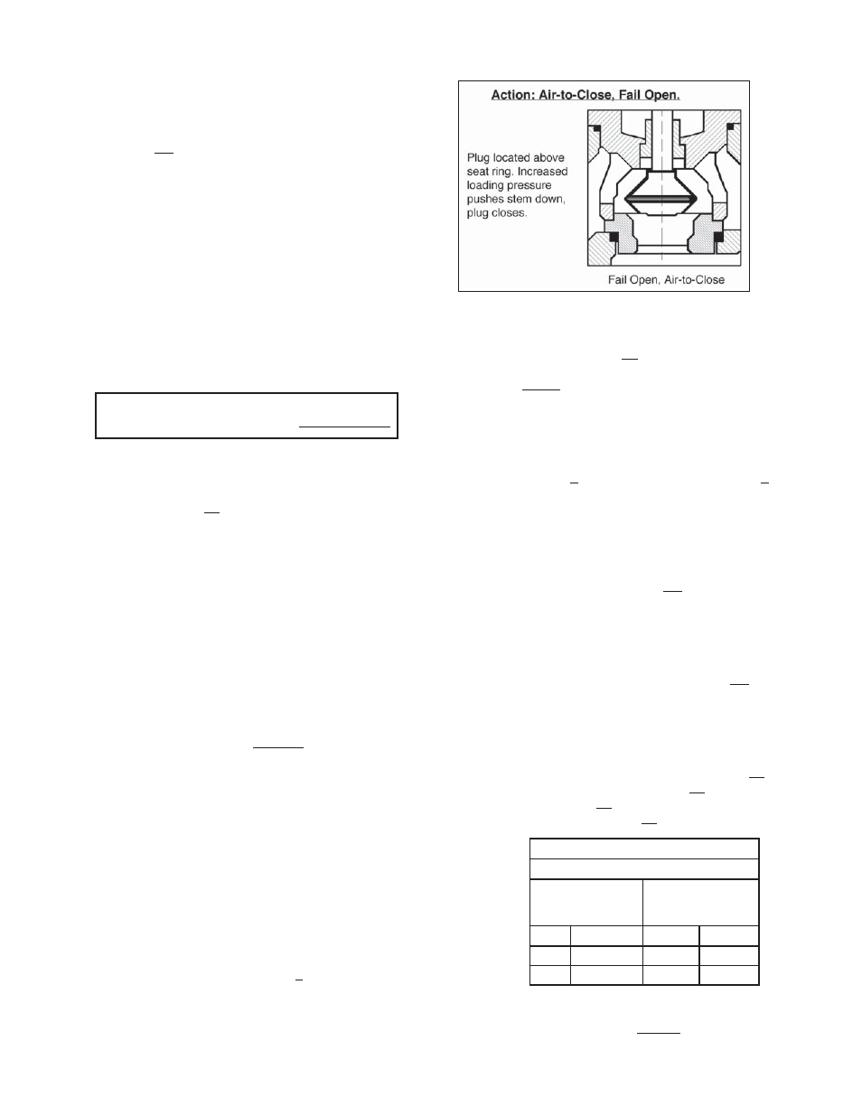
Figure 7: Air-to- Close Action
j. Reengage the valve stem (3) with the
ac tu a tor stem (19). Engage the num-
ber of rev o lu tions recorded in Step 8.c.,
minus the number of revs in di cat ed in
Table 1.
k. Tighten one jam nut (18) into po si tion.
l. Replace compression to ac tu a tor range
spring (6) by rotating spring adjustor (4)
CW (viewed from plug end) the num ber
of revs in di cat ed in the box of Step 3
pre vi ous. As the plug (3), and seat ring
(11) are “drawn to geth er”, make sure that
piec es are prop er ly aligned.
m. Lift actuator assembly (AA) and low er into
the body (1) cavity, aligning over bon net
studs (16)). Rest the bonnet (2) onto the
bonnet gasket (12).
n. Install nuts (17) onto bonnet bolt ing (16).
Wiggle the ac tu a tor assembly (AA) to
align all the moving parts. Wrench tight en
the bonnet bolting nuts (17) in al ter nat ing
cross-pat tern and in 1/2 rev o lu tion in cre-
ments until fully tightened.
9. Record changes on unit’s name plate (12).
Re move indicator plate screws (22) and ro tate
indicator plate (21) top to bottom. Re place
in di ca tor plate screws (22).
8. From ATC-FO to ATO-FC Ac tion:
a. With this action, the seat ring (11) re mains
in the body (1) when the actuator as sem bly
(AA) is re moved.
b. Loosen jam nuts (18). Loosen pack ing
fl ang e nuts (15).
NOTE: Take notice of the parts “dangling
loose ly” about the stem (3), the order of their
lo ca tion and their proper orientation.
c. Using soft-jawed pliers, grasp stem (3) just
below/at the threaded por tion, and rotate
the stem/plug as sem bly (3) CCW (viewed
from plug end) to re mov al. Record number
of rev o lu tions re quired to dis en gage and
record in the fol low ing box:
d. Partially withdraw the stem/plug as sem bly
(3) from the bonnet (2), tak ing care not to
drop the “dangling parts” - po si tion in di ca-
tor disc (20) and ((AP)), if in stalled.
e. Remove jam nuts (18). Ful ly with draw the
stem/plug as sem bly (3) from the bon net (2).
f. Lift out the seat ring (11) from the body
cavity. Re move the seat ring gasket (13).
Clean gasket fac ing sur fac es and in stall
new seat ring gas ket (13) and new bonnet
gasket (12) into body (1) re cess es.
g. Remove and replace packing rings (6) as
directed elsewhere in this sub-sec tion.
h. Place the seat ring (11) over the end of
the stem (3) in an inverted ori en ta tion from
the way re moved.
i. Insert the stem/plug assembly (3) back
into the bottom of the bonnet (2). Screw
both jam nuts (18) back onto stem (3), and
locate at the root of the thread por tion.
Re place all the “loose dan gling” parts back
in their prop er order and ori en ta tion.
NOTE: Reference the IOM for the po si tion er, as
the orientation/location of the ((AP)) may change.
If the action of the positioner does not change
when the valve unit’s ac tion is changed, the lo-
ca tion of the po si tion er unit will change from the
right side of the ac tu a tion yoke (1) to the left side,
or vice versa. This requires that the ac tu a tor be
rotated 180° from the be gin ning body-to-bon net
ori en ta tion, and that the po si tion er be re moved
and re-ori ent ed to an op po site po si tion.
TABLE 3
ATC-FO CONVERTED TO ATO-FC
Bench Set
Indicated
on Nameplate
New Bench Set
to be Utilized
psig
(Barg)
psig
(Barg)
3-13
(.21-.90)
5-15
(.34-1.0)
6-27
(.41-1.9)
9-30
(.61-2.1)
10. Modify fl ow direction arrow lo cat ed on body.
(Valve-Ac tu a tor Unit is always de signed with
Number of revolutions to disengage
valve stem from actuator stem: