Cashco 964 User Manual
Page 8
IOM-964
8
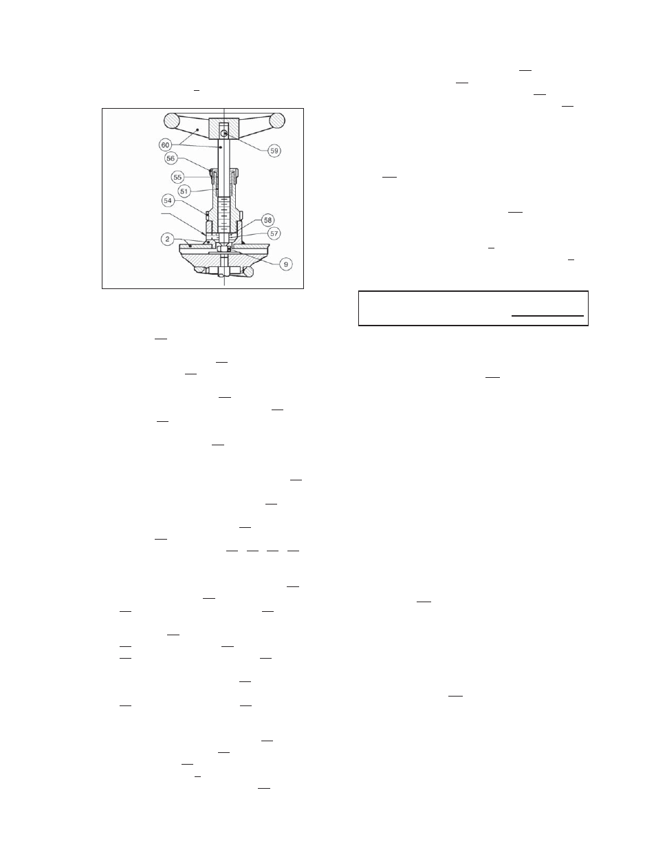
a. Place a wrench on the hex surface of pack-
ing box (54), and ham mer rap the wrench
CCW (viewed from top) to loosen. Fully
re move packing box (54) and hand wheel
sub as sem bly (60).
b. Remove grooved pin (57) from low er end
of handwheel sub-assembly stem (60) and
wash er (58).
c. Loosen packing nut (56) by ro tat ing CCW
(viewed from above) to dis en gage ment.
d. Remove handwheel sub-assembly (60)
fully out by ro tat ing CCW (viewed from
above). Lift out packing gland (55).
e. Remove old packing rope (51) from pack-
ing box (54) re cess and discard. Sol vent
clean all re moved parts (60) (54) (55) (56).
f. Lightly lubricate the thread ed por tion
of the handwheel sub-assembly (60),
place pack ing nut (56) and packing gland
(55) over the end of the stem (60) prop-
erly ori ent ed. Insert the handwheel sub-
assembly (60) back into the pack ing box
(54). Re place washer (58) on end of stem
(60) and reinsert grooved pin (57).
g. Lubricate the packing rope (51) with lith i um
grease and feed and press the pack ing
(51) into the pack ing box (54) re cess.
h. Lubricate both of the ex te ri or thread ed
por tions of the packing box (54). Re-
insert the pack ing box (54) with hand wheel
sub as sem bly (60) back into the con nec tion
of upper casing (2). Wrench-tight en and
ham mer rap the pack ing box (54).
4. Loosen all bonnet stud/bolt nuts (17) to re-
mov al.
5. Lift actuator assembly (AA) up wards ap prox i-
mate ly 8 inch es (200 mm), and lay hor i zon tal ly
on a work bench.
NOTE: When changing unit action, con sid er ation
should be given to re place ment of pack ing rings
(6). Bonnet gasket (12) and seat ring gasket (13)
are rec om mend ed for re place ment once the bon net
(2) and seat ring (11) have been re moved; re-use
of gas kets (12) (13) may allow fl uid leak age upon
reassembly and pres sur iza tion.
6. Remove bonnet gasket (12) from body (1)
re cess. Re move seat ring gasket (13) from
body (1) recess. Clean gasket facing sur fac es
in body (1) and on bonnet (2).
NOTE: The changing of unit action from direct
ATC-FO or from reverse ATO-FC ac tion is ac-
com plished not in the actuator, but in the body
by re vers ing the ori en ta tion of the plug (3) with
re spect to the seat ring (11). See Figures 6 and 7.
7. From ATO-FC to ATC-FO Ac tion:
a. With this action, the seat ring (11) is re-
tract ed from the body (1) when the ac tu a tor
assembly (AA) is re moved.
b. Loosen jam nuts (18). Loosen pack ing
fl ange nuts (15).
NOTE: Take notice of the parts “dangling loose ly”
about the stem (3), the or der of their lo ca tion and
their proper orientation.
F. Manual Handwheel Seal Re place ment:
1. Remove upper case (2) per section IV. E. steps
1 thru 4.
Number of revolutions required
to relax actuator range spring:
i.
Hand-tighten packing nut (56). Ro tate the
handwheel (60) in and out several times.
Wrench-tighten packing nut (56) only 1/4
of a rev o lu tion once the packing (51) is
prop er ly pressed into po si tion.
G. Reversing Unit Action:
1. Place body (1) into vise with ac tu a tor as sem bly
(AA) di rect ed upwards. Place matchmarks
be tween the bon net (2) and body (1).
2. Secure actuator assembly (AA) with an over-
head sup port capable of ver ti cal ly hoist ing.
3. Rotate spring adjustor (4) CCW (viewed from
plug end) until ac tu a tor's range spring (6) is
fully re laxed. Record the number of rev o lu-
tions required to loos en in the following box :
1/4" (DN8) NPT
(Signal Conn.)
Figure 5: Actuator Handwheel