Cashco 964 User Manual
Page 11
IOM-964
11
TABLE 4
Body Size
Number of Packing
Rings
inches
(DN)
2
(50)
9
3
(80)
9
the fl ow tending to push the plug open - FTO,
re gard less as to ATO-FC or ATC-FO ac tions.)
11. Wrench tighten packing to a min i mum of 12 ft/
lbs (16 N-M) torque. (NOTE: Field tight en ing
may be required to seal leak age.)
12. Tighten second jam nut (18).
H. Packing Replacement:
1. This requires that the ac tu a tor stem (19) be
sep a rat ed from the valve stem (3) to re place
pack ing (6).
4. Loosen screws (22) and po si tion the in di ca-
tor plate (21) at “S” (for shut); tight en screws
(22) to se cure in di ca tor plate (21). (NOTE:
Set the indicator plate (21) at the top edge
of the in di ca tor disc (20).)
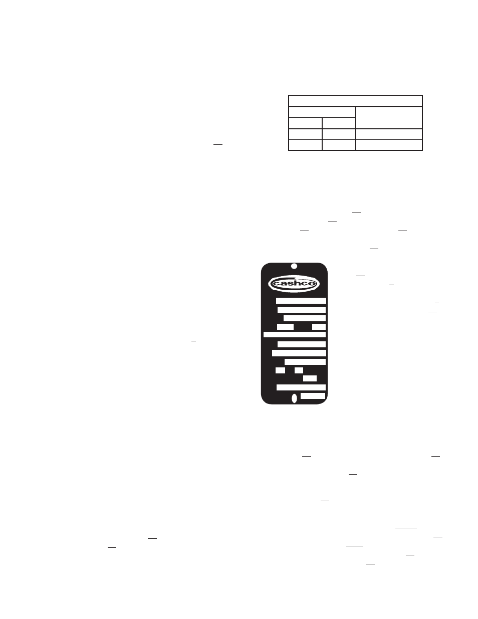
5. Reference
the
name
plate
(12) at tached to the ac tu a-
tor yoke (1). De ter mine
the bench set ting of the
in stalled range spring (6)
from the name plate (12);
i.e. 5-15 psig (.34-1.0
Barg), or 9-30 psig (.62-2.1
Barg).
6. Pressurize the actua-
tor to a pres sure level
2-3 psig (0.1-0.2 Barg)
above the upper pres sure
level of the bench set ting:
i.e. for 5-15 psig (.34-1.0
Barg) range, set pres sure
at 17-18 psig (1.2-1.3
Barg).
V. CALIBRATION
A. General:
1. This section covers cal i bra tion of the con trol
valve unit. Cal i bra tion consists of ad just ing
stroke length and bench set ting.
2. Positioner, if installed, re quires ref er ence to
the spe cifi c po si tion er model IOM for prop er
cal i bra tion pro ce dure.
3. All indicated Item Num bers that are with re-
spect to IOM-964 and are part of “body” will
be in single pa ren the sis; i.e (2). Those that
are part of the 964 actuator will be in single
pa ren the sis and un der scored; (2). Those that
are part of the po si tion er IOM will be in double
pa ren the sis; i.e. ((AP)).
4. Following procedures assumes as sem bled
valve unit has been removed from the pipe-
line where installed and all main te nance has
been com plet ed per in struc tions of Sec tion IV
preceeding.
B. Procedure – Reverse Action, ATO-FC:
1. Place body (1) in a vise with ac tu a tor as sem bly
(AA) directed upwards.
2. Connect a temporary air supply with an in-line
ad just able airset regulator with gauge to the
actuator top works con nec tion.
3. Loosen lower stem jam nut (18) by ro tat ing
CCW (viewed from plug end) 2-3 rev o lu tions.
Using upper stem jam nut (18), fi rmly lo cate
the in di ca tor disc (20) up against the ac tu a tor
stem (19) bot tom.
7. Observe the position of the in di ca tor disc
(20) on the scale of the in di ca tor plate (21),
making sure to use the “top edge” of the
in di ca tor disc (20) as the ref er ence point. If
the position in di cat ed is not exactly at “O” (for
“open”), then the valve stem (3)-to-ac tu a tor
stem (19) com bined length is in cor rect, and
must be ad just ed.
8. a. If travel indicator stops above the “O”
po si tion, the com bined stem (3, 19)
length is short. Loos en jam nut (18)
hold ing the in di ca tor disc (20) against
ac tu a tor stem (19).
SN
SIZE
MODEL
FAIL
TRIM
Cv
BENCH
ACT.
MAX WORK ∆P
TAG
STROKE
BODY
psig Max
IN
2
SECTION V
2. Follow procedure in Steps IV. D.1 through
IV. D. 15., and Steps IV. D. 24. through 39.
3. The number of packing rings (6) is as re-
cord ed in Table 4 below: