Caution – Cashco 964 User Manual
Page 14
IOM-964
14
VII. TROUBLE - SHOOTING GUIDE
SECTION VII
Hereafter, the procedure as sumes that ac tu al
fl uid fl ow may be established. This may not
be practical / pos si ble in all cas es; if so, vary
procedure as re quired.
3. Start with either of the two block valves closed,
with the other open. The bypass valve should
be closed. Pres sur ize sys tem, if pos si ble/
prac ti cal.
4. Back out the airset’s adjusting screw until
loose.
5. Turn on air supply pressure.
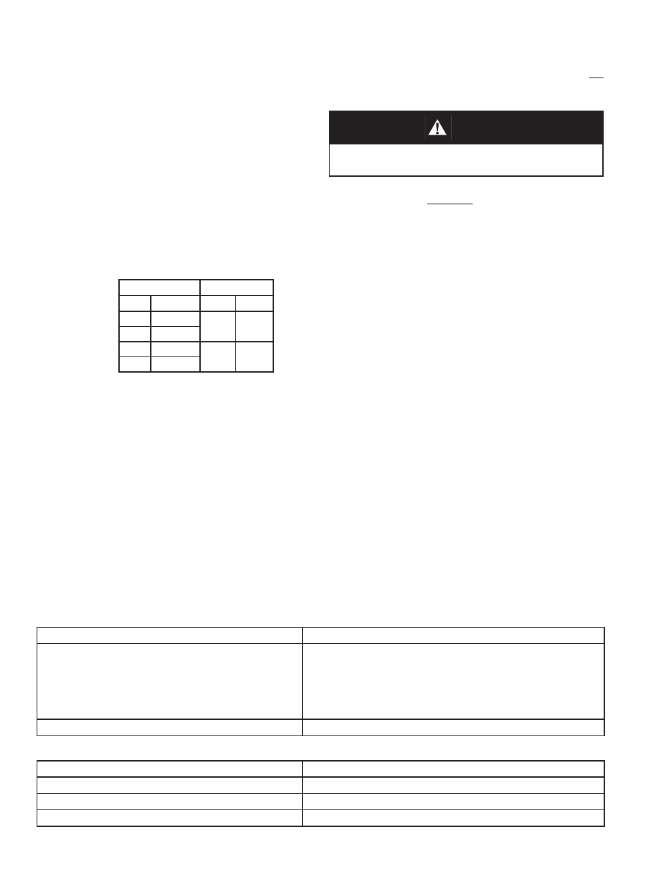
6. Adjust the air supply airset (fi l ter-reg u la tor) to
the proper lev el as in di cat ed in the following
table.
NOTE: DO NOT STROKE THE CON TROL VALVE WITH
AN AIR SUP PLY PRES SURE SET TING GREAT ER THAN
REC OM MEND ED MAX I MUM PRES SURE!
7. Place loop controller into “man u al” mode. Vary
setting from minimum - mid-range - max i mum
SIG output. Ob serve re sponse of con trol
valve unit to these chang es of input SIG. The
valve should fully stroke at the vari a tion from
min i mum SIG to max i mum SIG; the mid-range
SIG should have the valve stem travel at/near
1/2 open.
8. Confi rm that action of con trol ler and po si tion er
- direct or reverse - are producing the de sired
re sponse in the con trol unit. Con fi rm that the
con trol valve “fail” po si tion is as re quired.
Bench Setting
Airset Output
psig
(Barg)
psig
(Barg)
5-15
(.34-1.0)
20
(1.4)
3-13
(.21-.90)
9-30
(.61-2.1)
35
(2.4)
6-27
(.41-1.9)
CAUTION
DO NOT WALK AWAY AND LEAVE A MAN U AL LY
CONTROLLED CON TROL VALVE UN AT TEND ED!
Possible Causes
Remedies
A.
Excess packing friction.
A1.
A2.
A3.
A4.
A5.
Realign body - stem - actuator.
Packing follower too tight for optional packing designs.
Install positioner.
Increase bench set by changing to stiffer actuator range
spring. Will require positioner if not installed. May require
different airset.
B.
Installed backwards.
B.
Install per fl ow arrow.
1. Valve is “jumpy” in stroking.
Possible Causes
Remedies
A.
Excess pressure drop.
A.
Bring pressure drop within design limits.
B.
Guide bushing wear.
B.
Re place guide bushing.
C. Misalignment.
C.
Realign body-stem-actuator.
2. Valve makes “screeching” noise.
9. Always “heat” or “cool” down the system
pip ing SLOW LY by open ing the control valve
sta tion by pass valve in small in cre ments.
10. With one of the control valve station block
valves still closed, and the loop con trol ler
still in “man u al” mode, open by pass valve
and vary fl ow rate man u al ly to ob serve the
re sponse of the con trol ler and control valve
unit to geth er.
11. Attempt to develop manual con trol of the
loop by opening/clos ing the man u al by pass
as re quired, or by manually con trol ling main-
stream fl ow as re quired.
12. When control valve is partially open, crack
open slowly the closed block valve while
si mul ta neous ly clos ing the by pass valve.
Con tin ue this pro ce dure until the bypass is
closed and the block valves are both fully
open. The system is still under “man u al”
mode control, but all fl ow is pass ing through
the control valve.
13. Vary controller “manual” SIG output until
match ing the “au to mat ic” SIG output, then
change the mode of the controller over to
“automatic”, and the loop will ex pe ri ence a
min i mum of upset con di tions, and will be in
au to mat ic control.